Energy output structure of panel vacuum electron device

A vacuum electronic device and energy output technology, which is applied to the circuit components of transit time type electron tubes, traveling wave tubes, etc., can solve problems such as reducing device efficiency, affecting power amplification and energy output, and closing the collector entrance. The effect of easy processing, simple structure and high output efficiency

Inactive Publication Date: 2012-11-21
UNIV OF ELECTRONICS SCI & TECH OF CHINA
View PDF2 Cites 11 Cited by
  • Summary
  • Abstract
  • Description
  • Claims
  • Application Information

AI Technical Summary

Problems solved by technology

[0005] For the high-power strip-shaped electron beam vacuum electronic device, it is not feasible to adopt the above-mentioned vertical and horizontal energy output methods, because the ring-shaped electron beam has an axisymmetric structure, and the electrons can be hit on the side wall by defocusing. , does not affect the output of the TM field, while the strip-shaped electron beam will diverge in all directions through defocusing, and the electron beam on the axis of the magnetic field may even hit the output window directly without being affected by defocusing, seriously affecting the power amplification. and energy output; while using horizontal energy output, because the band-shaped electron beam has a certain width, if the collector is to efficiently collect electron beams, the collector entrance is relatively wide, and the collector entrance cannot be used to enlarge the TM Field cutoff, such as figure 1 In the 36GHz return wave oscillator, the strip-shaped electron column is 1mm thick and 30mm wide. When the smallest collector entrance is the same size as the electron beam, the corresponding cutoff frequency is 3.26GHz, which cannot cut off the oscillating 36GHz frequency millimeter wave. It also makes most of the power into the collector and is attenuated, which greatly reduces the efficiency of the device and makes the collector extremely easy to burn out.

Method used


Image

  • Energy output structure of panel vacuum electron device
  • Energy output structure of panel vacuum electron device
  • Energy output structure of panel vacuum electron device

Examples


Embodiment 1

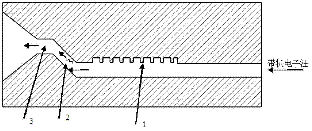
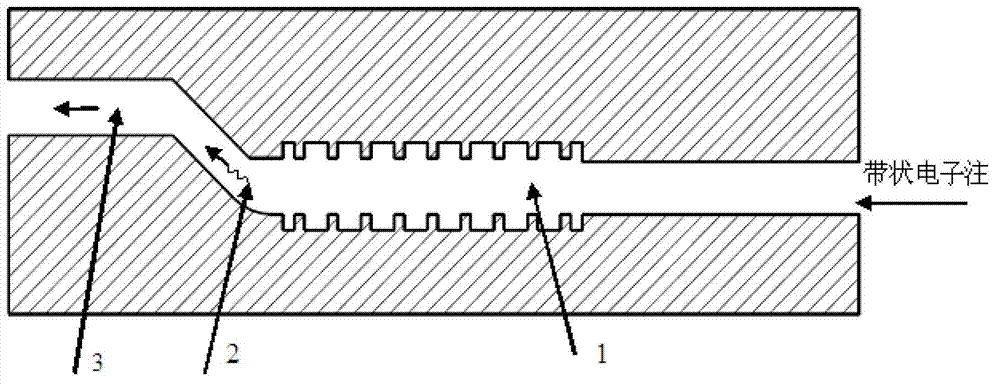
[0022] Embodiment 1: The planar slow-wave structure adopts a rectangular double-grid slow-wave structure. According to the parameters of the rectangular double-grid, the height of the energy output structure is 4mm and the width is 46mm. Through calculation, a circular arc transition (with a radius of 4 mm) is adopted, and the angle between the energy output structure and the slow wave structure is 45 degrees. The electron beam interacts with the rectangular double-gate structure to generate high-power millimeter wave oscillation, and then the TE wave is output from the energy output structure. The whole device generates high power oscillation output at 36GHz such as Figure 5 shown (measured at image 3 far left of the energy output structure shown).

Embodiment 2

[0023] Example 2: The slow-wave structure adopts a sinusoidal waveguide grating (single-grid or double-grid) slow-wave structure, and other structures remain unchanged. Through optimal design, the angle between the rectangular oblique waveguide 2 and the planar sinusoidal waveguide grating slow-wave structure 1 is 30 degrees, the output energy is output along the rectangular straight waveguide 3 .

Embodiment 3

[0024] Embodiment 3: The slow wave structure adopts the trapezoidal grid (single grid or double grid) slow wave structure, and other structures remain unchanged. Through optimized design, the angle between the rectangular inclined waveguide 2 and the flat trapezoidal grid slow wave structure is 60 degrees. The output energy is output along the rectangular straight waveguide 3 .


PUM


Abstract

An energy output structure of a panel vacuum electron device belongs to the technical field of vacuum electronics. The energy output structure of the panel vacuum electron device comprises a panel slow wave structure (1), rectangular inclined waveguide (2) and rectangular straight waveguide (3). The sizes of narrow sides and wide sides of the panel slow wave structure (1), the rectangular inclined waveguide (2) and the rectangular straight waveguide (3) are uniform, the rectangular straight waveguide (3) is parallel to the panel slow wave structure (1), and two ends of the rectangular inclined waveguide (2) are connected with the rectangular straight waveguide (3) and the panel slow wave structure (1) respectively in inclined mode. The energy output structure solves the problems of electron collection and energy output of the high-power panel vacuum electron device, achieves integration of a collector and the energy output structure, and is simple in structure, easy to machine and high in output efficiency.

Description

technical field [0001] The invention belongs to the technical field of vacuum electronics, and relates to a traveling wave tube amplifier and a return wave oscillation device. Background technique [0002] With the advancement of science and technology, the demand for vacuum electronic devices tends to be higher power and frequency, so high-power, high-frequency vacuum electronic devices have become a research hotspot at home and abroad. However, to achieve higher power requires electron beams to be able to transmit larger currents, and to achieve higher frequencies requires slow-wave structures to become smaller as frequency increases (ie, size co-passing effect), while the existing permanent The magnetic focusing ability is limited. As the current increases, the cross section of the conventional cylindrical electron beam decreases with the slow wave structure, and its space charge field increases sharply, so that the permanent magnetic field is not enough to focus the cyli...

Claims


Application Information

Patent Timeline
Patent Type & Authority Applications(China)
IPC IPC(8): H01J23/24H01J25/34
Inventor 王战亮宫玉彬魏彦玉段兆云
Owner UNIV OF ELECTRONICS SCI & TECH OF CHINA
Why Eureka
Try Eureka