Heat insulation/heat dissipation sheet and intra-device structure

A technology in a heat sink and a device is applied in the field of adiabatic heat sinks and the internal structure of the device, which can solve the problems of difficulty in ensuring the space of heat dissipation components, malfunction, burns, etc., and achieve the effect of preventing excessive heat reception.

Inactive Publication Date: 2012-11-21
NITTO DENKO CORP
View PDF6 Cites 23 Cited by
  • Summary
  • Abstract
  • Description
  • Claims
  • Application Information

AI Technical Summary

Problems solved by technology

Therefore, it is difficult to secure a space for installing heat-dissipating components such as a radiator, and sometimes the heat generated by heat-generating components such as IC elements in the CPU is directly released to the housing via the heat-conducting member.
In this case, there is a problem that the outside of the case is locally heated due to the heat of the heat-generating component being conducted to the outside of the case, or burns are caused due to prolonged contact with the human body.
In addition, there is such a problem that with high-density mounting, components that are sensitive to heat, control ICs of other systems, etc. are in the vicinity of heat-generating components, and receive heat from adjacent heat-generating components, causing adverse effects such as malfunction and life reduction
[0011] Also, in Patent Document 3, there is no description as to how much the heat of the heat-generating component can be reduced and how much the heat conduction to the case can be suppressed, and there are many uncertainties about the effect.

Method used


Image

  • Heat insulation/heat dissipation sheet and intra-device structure
  • Heat insulation/heat dissipation sheet and intra-device structure
  • Heat insulation/heat dissipation sheet and intra-device structure

Examples


Embodiment 1

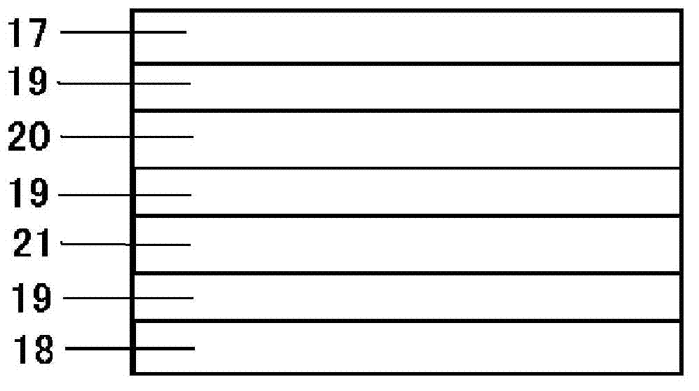
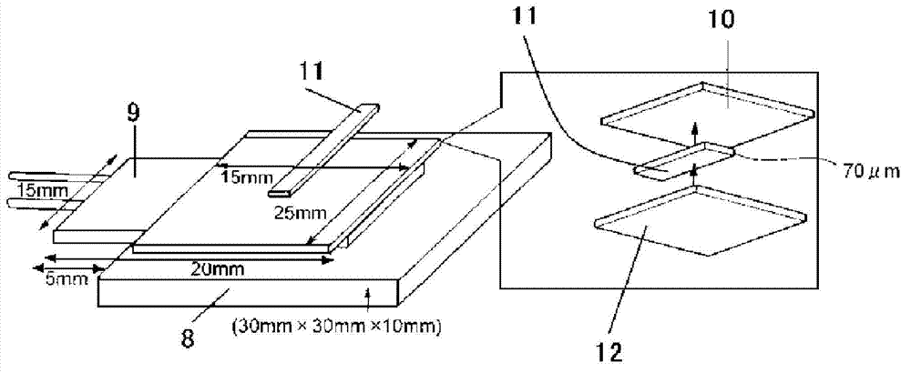
[0104] Use thickness 1.0mm, thermal resistance 20.26cm 2 ・K / W polyethylene foam sheet (manufactured by Sekisui Chemical Industry Co., Ltd., SOFTLON S (Japanese: ソフトロン S) #1001) is used as a heat insulating layer, and a synthetic rubber-like adhesive with a thickness of 0.10 mm is formed on both sides. Adhesive layer. Paste on one adhesive surface formed on the heat insulating layer as a heat conduction layer with a thickness of 0.040mm and a thermal resistance of 1.13cm 2 ・K / W aluminum foil (manufactured by Sumamigaru Aluminum Foil Co., Ltd., BESPA (Japanese: べスパー)). Thereafter, in order to perform heat dissipation and heat insulation evaluation, the other adhesive surface formed on the heat insulating layer was stuck to an acrylic plate having a size of 30 mm in length and 30 mm in width. At this time, a chip type thermocouple was installed between the sample and the acrylic plate so that the temperature of the test piece could be measured. After that, use a thickness of 0...

Embodiment 2

[0106] In addition to changing the heat conduction layer in Example 1 to a thickness of 0.025mm and a thermal resistance of 0.35cm 2 - Evaluation was performed in the same manner as in Example 1 except for a K / W graphite sheet (manufactured by Panasonic Denko Co., Ltd., EYGS182303).

Embodiment 3

[0108] In addition to changing the heat conduction layer in Example 1 to a thickness of 0.035mm and a thermal resistance of 1.46cm 2 - Except the copper foil of K / W, it evaluated similarly to Example 1 other than that.


PUM


Abstract

The invention provides a heat insulation / heat dissipation sheet and an intra-device structure. The purpose of the present invention is to efficiently dissipate heat generated from a heat generating component of an electronic device, a battery, a heat generating machine component or the like each having the heat generating component mounted on a circuit board or the like, while simultaneously preventing a component to be protected, which is adjacent to the heat generating component, from being heated and thereby being deteriorated in the performance, by suppressing transmission of the heat to the component to be protected. Therefore, specifically disclosed is a heat insulation / heat dissipation sheet, which is arranged between a heat generating component and a component to be protected that is adjacent to the heat generating component for the purpose of connecting the components with each other, and in which an adhesive layer or a heat conductive adhesive layer, a heat conductive layer, an adhesive layer or a heat insulating adhesive layer, a heat insulating layer, and an adhesive layer or a heat insulating adhesive layer are laminated in this order. In addition, an intra-device structure is obtained by bonding the heat conductive layer-side adhesive layer of the heat insulation / heat dissipation sheet to a heat generating component, while bonding the heat insulating layer-side adhesive layer to a component to be protected.

Description

technical field [0001] The present invention relates to a heat insulating heat sink and a device structure using the heat insulating heat sink. Efficiently dissipate heat generated by heat-generating components and secondary batteries in general devices other than equipment, and suppress heat conduction to components, equipment, and devices adjacent to heat-generating components. Background technique [0002] In electronic devices such as home appliances and mobile phones, heat dissipation measures to dissipate heat generated inside are becoming more and more important for improving product reliability. However, in recent years, the miniaturization of equipment has progressed, and components have been arranged at high density in a small space. Therefore, it is difficult to secure a space for disposing a heat dissipation member such as a heat sink, and the heat generated by a heat generating component such as an IC element in the CPU may be directly dissipated to the case th...

Claims


Application Information

Patent Timeline
Patent Type & Authority Applications(China)
IPC IPC(8): H01L23/36H05K7/20
CPCH01L2924/0002H01L23/433H01L23/36H01L23/3737H01L2924/09701Y10T428/31612Y10T428/31913Y10T428/31587Y10T428/31641Y10T428/31667Y10T428/31598Y10T428/31935Y10T428/31826Y10T428/31707Y10T428/31569Y10T428/31663Y10T428/31699Y10T428/31601Y10T428/31605Y10T428/31649H01L2924/00H05K7/20
Inventor 铃木秀典三栗野幸一
Owner NITTO DENKO CORP
Why Eureka
Try Eureka