Fan diffuser structure for dust collector

A diffuser, vacuum cleaner technology, applied in vacuum cleaners, machines/engines, components of pumping devices for elastic fluids, etc., can solve the problems of low flow efficiency, loss of flow energy, high air flow rate, etc., to achieve uniform airflow speed The effect of distribution, increasing space and floor area, reducing energy loss

Inactive Publication Date: 2012-11-28
LG ELECTRONICS (TIANJIN) APPLIANCES CO LTD
View PDF8 Cites 3 Cited by
  • Summary
  • Abstract
  • Description
  • Claims
  • Application Information

AI Technical Summary

Problems solved by technology

[0010] However, in the fan motor unit for vacuum cleaners as described above, the air flow between the leading vanes 11 of the diffuser 8 forms a flow velocity difference between the middle part on the flow channel and the two side parts near the leading vanes, that is, the air velocity in the middle part is fast. , the pressure is high, the air flow velocity on both sides is slow, and the pressure is low. Due to the uneven air velocity, the pressure distribution is uneven, which will cause eddy currents, thereby losing flow energy and low flow efficiency.

Method used


Image

  • Fan diffuser structure for dust collector
  • Fan diffuser structure for dust collector
  • Fan diffuser structure for dust collector

Examples


Embodiment Construction

[0034] The present invention will be described in detail below with reference to the drawings and examples. The same symbols are used for the same components in the present invention as in the prior art.

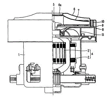
[0035] The fan diffuser structure of the present invention is arranged in such as figure 1 In the shown vacuum cleaner fan motor unit, the fan motor unit includes a motor casing 1 with an opening formed at the upper end, and a motor 4 composed of a stator 2 and a rotor 3 is arranged inside the motor casing 1; it is inserted into the center of the rotor 3 up and down part, and rotate together with the rotor 3, and provide the rotating shaft 5 for the rotor 3 to rotate power.

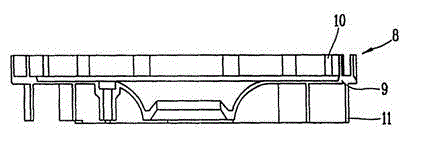
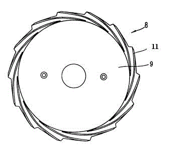
[0036] A fan housing 6 having a suction port 6a formed in the center is coupled to the upper opening portion of the motor housing 1 . The inside of the fan casing 6 is provided with a fan 7 that is coupled to the rotating shaft 5 and sucks in air through the suction port 6a, and there is a diffuser th...


PUM


Abstract

The invention discloses a fan diffuser structure for a dust collector. The fan diffuser structure comprises a body part with certain thickness and a certain area; a plurality of arc front guide blades are formed at the periphery of the lower side of the body part at certain intervals; a flow channel through which air is guided to flow is formed between two adjacent front guide blades; and a groove is formed on the bottom of each flow channel. The fan diffuser structure for the dust collector has the advantages that the groove is formed in the center of the bottom of the flow channel formed between the adjacent two front guide blades, and the areas of the cross sections of the grooves and the flow channels are gradually reduced from external openings to internal openings proportionably. After the air flow enters the flow channels, the spaces and the bottom areas of the flow channels are increased due to the grooves formed in the centers of the flow channels, so that the flow speed of the air flow in the middles is reduced, the difference of the flow speed in the middles and two sides of the flow channels is balanced, the air flow speed in the flow channels is distributed uniformly, eddy current can be reduced effectively, energy loss is reduced, and flowing efficiency is improved.

Description

technical field [0001] The invention belongs to the field of vacuum cleaners, and in particular relates to a vacuum cleaner fan diffuser structure in which a groove is arranged at the center of the bottom of the flow channel. Background technique [0002] Vacuum suction is a cleaning and sanitary appliance used to remove dust from floors, carpets, walls, furniture, clothing and various gaps. Vacuum cleaners generally include a vacuum cleaner motor that generates suction from an imported power supply, a motor inlet that forms an air path system, a suction nozzle, a hose, and a dust collection device that collects inhaled matter. [0003] According to the shape of vacuum cleaners, they can be divided into upright vacuum cleaners, horizontal vacuum cleaners and portable vacuum cleaners. Generally speaking, the upright vacuum cleaner includes a front cover, a rear cover and a bottom case. There is a vacuum hose connection device on the top of the front cover, a horizontal wire...

Claims


Application Information

Patent Timeline
Patent Type & Authority Applications(China)
IPC IPC(8): A47L9/00F04D29/44
Inventor 杨攀
Owner LG ELECTRONICS (TIANJIN) APPLIANCES CO LTD
Why Eureka
Try Eureka