Al technical title is built by PatSnap Al team. It summarizes the technical point description of the patent document.
A closed, fixed plate technology, used in forging/pressing/hammer devices, manufacturing tools, forging/pressing/hammering machines, etc., can solve problems affecting device stability, unbalanced punch force, and corporate losses. Achieve the effect of strong practicability, high stability, and guaranteeing machining accuracy
Active Publication Date: 2013-06-26
张家港爱斯诺机械密封有限公司
View PDF5 Cites 0 Cited by
Summary
Abstract
Description
Claims
Application Information
AI Technical Summary
This helps you quickly interpret patents by identifying the three key elements:
Problems solved by technology
Method used
Benefits of technology
Problems solved by technology
[0004] In this structure, the movement of the upper and lower touch fixing plates and the fixing of the left and right punches are all connected to the columns or side walls on both sides of the formwork, so that the columns or side walls are subjected to excessive bending force, which affects the stability of the entire device and the practicability. Not strong; in addition, the left and right punches will also be affected when the force is applied, resulting in unbalanced punch strength, affecting the processing quality, and causing unnecessary losses to the enterprise
Method used
Image
Click on the blue label to locate the original text in one second.
Reading with bidirectional positioning of images and text.
Examples
Embodiment Construction
[0018] The present invention will now be described in further detail in conjunction with the accompanying drawings and preferred embodiments. These drawings are all simplified schematic diagrams, which only illustrate the basic structure of the present invention in a schematic manner, so they only show the configurations related to the present invention.
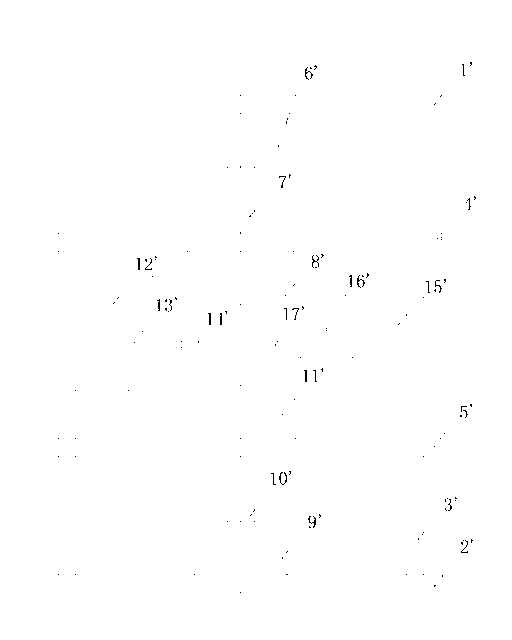
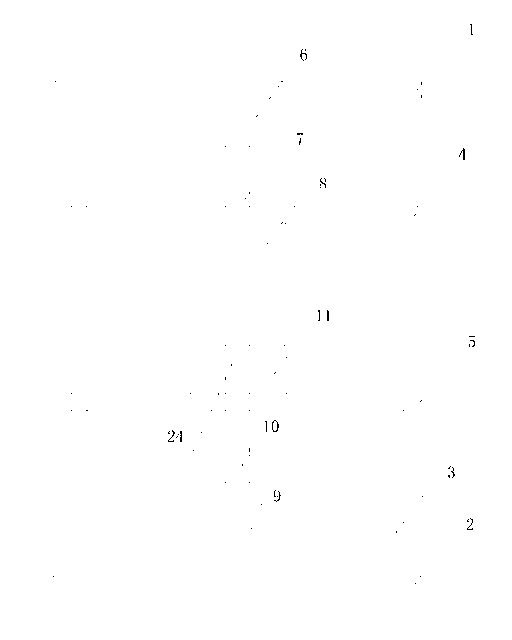
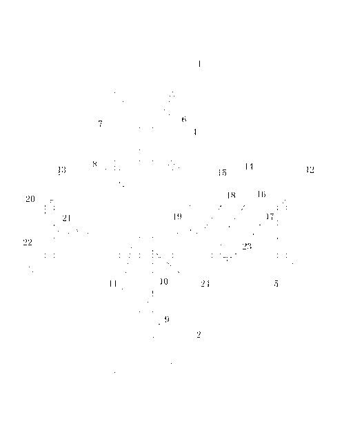
[0019] Such as Figure 2-3 As shown, a closed forging device includes a mold base, an upper die 8, a lower die 11 opposite to the upper die 8, an upper die fixing plate 4 that fixes the upper die 8 below the plate body, and fixes the lower die 11 The lower mold fixed plate 5 above the plate body, the upper mold fixed plate 4 and the lower mold fixed plate 5 are respectively fixed on the mold base, and the mold base includes the mold base upper plate 1, the mold base lower plate 2 and is fixed on the mold base. The columns 3 at both ends of the upper mold base plate 1 and the lower mold base plate 2, the two ends of the uppe...
PUM
Abstract
The invention relates to a sealed forging device, wherein two ends of an upper die fixing plate and a lower die fixing plate are respectively connected with a vertical column and are arranged between a die frame upper plate and a die frame lower plate; two ends of the upper die fixing plate are movably connected with the vertical column; two ends of the lower die fixing plate are fixedly connected with the vertical column; an upper cylinder fixed at the die frame upper plate is arranged between the die frame upper plate and the upper die fixing plate; an upper cylinder piston rod connected with the upper die fixing plate is fixedly arranged on the upper cylinder; a material jacking device which is matched with a lower die is arranged between the die frame lower plate and the lower die fixing plate; and a die punching device is further fixedly arranged on the lower die fixing plate. When the vertical column on the die frame is mainly stressed, only the upper die fixing plate is moved but the lower die fixing plate is arranged on the vertical column and is not moved; left and right punching heads are also fixed through a left baffle plate and a moving baffle plate and are moved through a slide rod; according to the structure, a bending force implemented on the vertical column on the die frame is completely canceled, so that the whole device is higher in stability and stronger inpracticability, and moreover the machining precision and the quality of a workpiece are ensured.
Description
technical field [0001] The invention relates to a forging device, in particular to a closed forging device. Background technique [0002] At present, the existing devices for forging dies in the market have typical structures such as figure 1 As shown, among them, 1', the upper plate of the formwork, 2', the lower plate of the formwork, 3', the side wall, 4', the fixing plate of the upper mold, 5', the fixing plate of the lower mold, 6', the upper cylinder, 7 ', upper cylinder piston rod, 8', upper mold, 9', lower cylinder, 10', lower cylinder piston rod, 11', lower mold, 12', left cylinder, 13', left cylinder piston rod, 14 ’, the left punch, 15’, the right cylinder, 16’, the piston rod of the right cylinder, 17’, the right punch. [0003] Its working principle is: the fixed plate of the upper mold and the fixed plate of the lower mold can move along the column, after the upper and lower oil cylinders are filled with oil, the upper and lower molds can be closed; The pist...
Claims
Application Information
Patent Timeline
Application Date:The date an application was filed.
Publication Date:The date a patent or application was officially published.
First Publication Date:The earliest publication date of a patent with the same application number.
Issue Date:Publication date of the patent grant document.
PCT Entry Date:The Entry date of PCT National Phase.
Estimated Expiry Date:The statutory expiry date of a patent right according to the Patent Law, and it is the longest term of protection that the patent right can achieve without the termination of the patent right due to other reasons(Term extension factor has been taken into account ).
Invalid Date:Actual expiry date is based on effective date or publication date of legal transaction data of invalid patent.