Low-lamp-position multi-dimensional road lighting system

A lighting method and low light level technology, applied in the field of low light level multi-dimensional road lighting methods, can solve the problems of driver's visual fatigue, low road brightness uniformity, can not really eliminate glare, etc., and achieve the effect of maximizing efficiency

Active Publication Date: 2012-11-28
SHENZHEN UNIV
View PDF5 Cites 12 Cited by
  • Summary
  • Abstract
  • Description
  • Claims
  • Application Information

AI Technical Summary

Problems solved by technology

[0009] (2) Invalid lighting problem
[0015] Therefore, the current mainstream lighting methods have a large proportion of ineffective lighting and the problem of violating the basic needs of lighting.
[0016] (3) Low visibility problem
[0036] 2. Low level of visibility
[0037] In this low-light level lighting method, the same light source and lamp are used for the reverse and the same direction lighting components, the chromaticity is the same, and the lighting space is not independent. It is impossible to form a high brightness contrast and chromaticity contrast between the road background and the front object, and the road surface The brightness uniformity of th...

Method used


Image

  • Low-lamp-position multi-dimensional road lighting system
  • Low-lamp-position multi-dimensional road lighting system
  • Low-lamp-position multi-dimensional road lighting system

Examples


Embodiment Construction

[0101] The present invention will be further described below in conjunction with the examples. It should be understood that the examples are only for the purpose of illustration, and in no way limit the protection scope of the present invention.

[0102] The process of optimizing the design of road lighting by applying low-light-level multi-dimensional lighting is as follows:

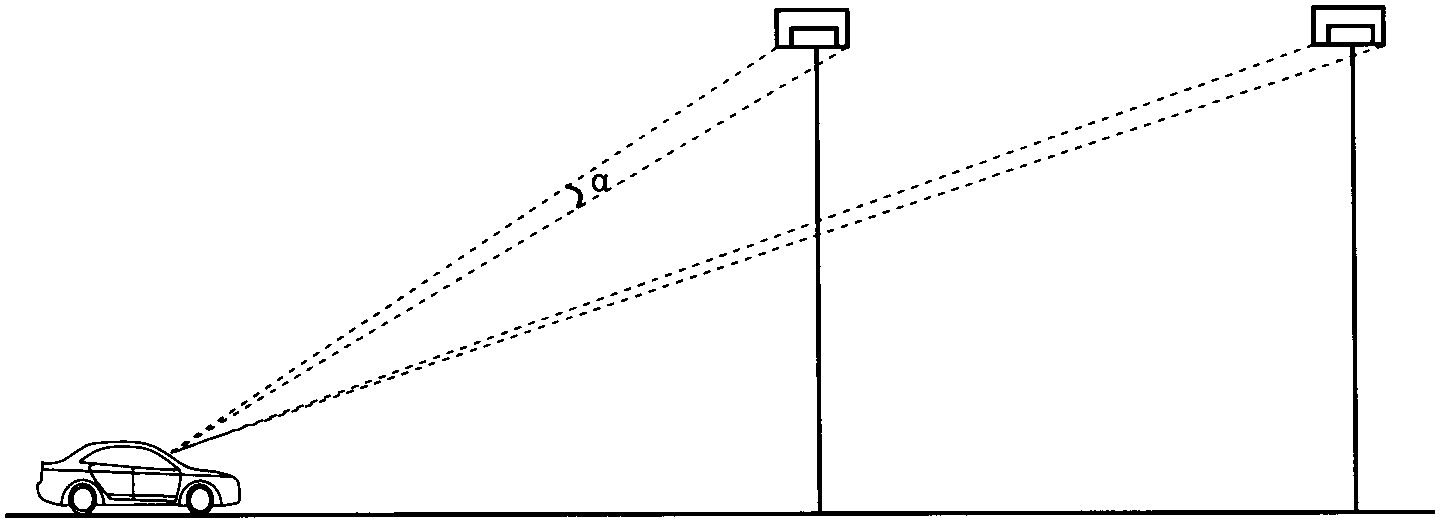
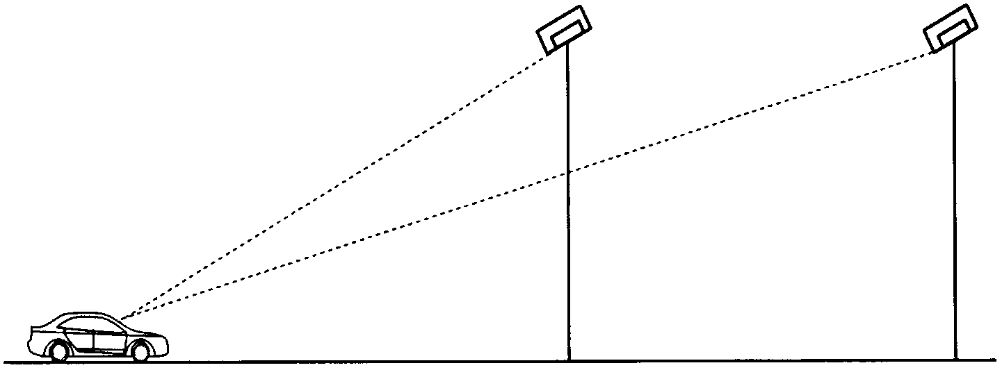
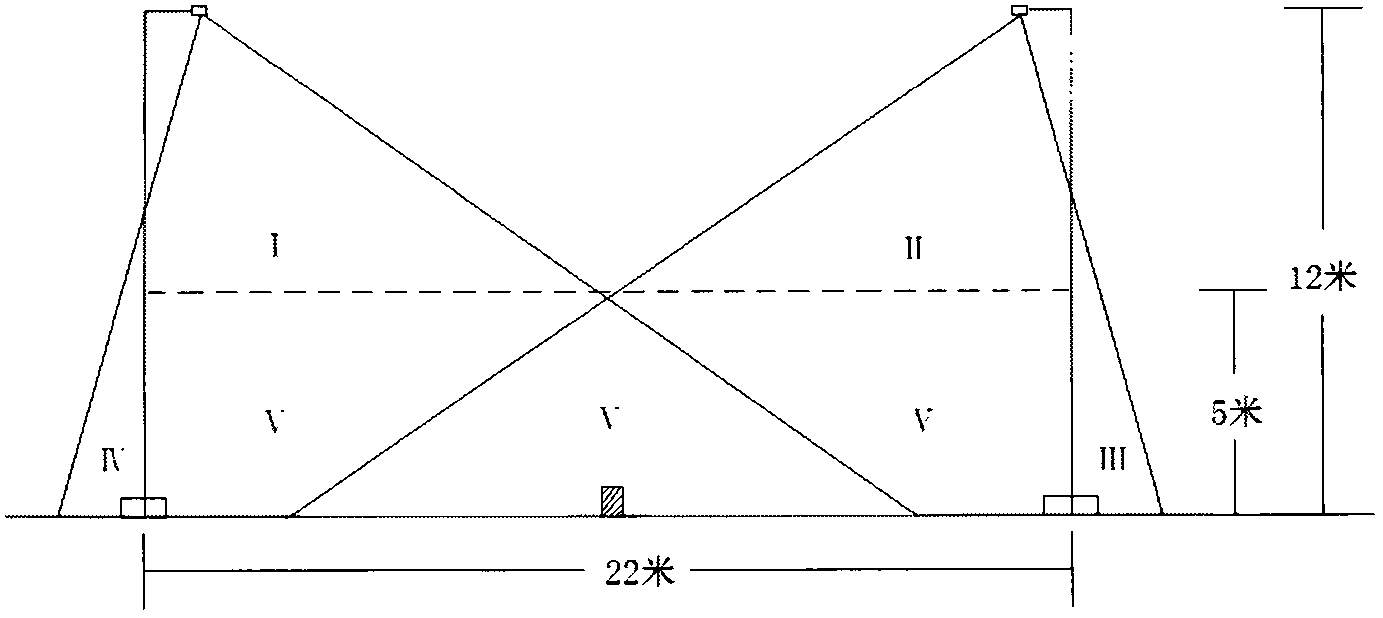
[0103] 1. On a section of closed expressway, determine the upper limit of the power density of this type of road according to the design specifications, arrange the lights according to the multi-dimensional lighting method of low light position, and select the light height, light distance, single light power and light distribution according to experience Light source and lamp parameters such as curves;

[0104] 2. Calculate the lighting parameters such as road surface brightness, uniformity, space illuminance, uniformity, glare index, and visibility index according to the above parameters;

[0105] 3. ...


PUM


Abstract

The invention provides a low-lamp-position multi-dimensional road lighting system which comprises multiple dimensions of lighting components, including a backward lighting component, a forward lighting component, a transverse lighting component and a vertical lighting component. The lighting function, the photochromic range, the irradiation direction and the irradiation space of each lighting component are respectively independent and can be adjusted independently. According to the task nature, each component is provided with independently operating special light source and lamp installed at low position. The low-lamp-position multi-dimensional road lighting system respectively undertakes the tasks of road surface lighting, space lighting, complex weather lighting and guidance lighting tasks. In each task, the efficiency of the low-lamp-position multi-dimensional road lighting system is maximized, and the overall lighting reaches comprehensively optimal. The invention overcomes the defects of the traditional high-lamp-position lighting system and the traditional low-lamp-position lighting system, so that the light sources and the lamps with different purposes perform own duties, the problems of glare, ineffective lighting, poor longitudinal uniformity degree and the like are effectively solved, and the lighting efficiency is greatly improved. The low-lamp-position multi-dimensional road lighting system is autonomously applied and researched based on the characteristics of a small-power high-light-efficiency light source per se, the lighting system of the traditional projection lamp is radically discarded, and the mode of simply replacing the HPS (High Pressure Sodium) lamp with an LED lamp is also discarded.

Description

technical field [0001] The present invention is the first part of the inventor's series of inventions - "multi-dimensional road lighting system", and relates to a new road lighting method, specifically a low-light multi-dimensional road lighting method. Background technique [0002] At present, the general lighting method of expressway and highway lighting is to use high-light street lamps, the light source is HPS, the installation height is about 10m, the installation distance is about 30m, and the single lamp power is about 250W. This lighting method constitutes the current mainstream lighting method. This lighting method is mature in technology, but due to the high lamp position and high power of a single lamp, there are the following problems: [0003] 1. Glare problem [0004] The road lighting design specification requires the use of cut-off and half-cut street lights to reduce glare. This measure can limit glare but not eliminate it. The reason for glare is: taking...

Claims


Application Information

Patent Timeline
IPC IPC(8): F21S8/08F21V14/00F21V23/00F21W131/103
CPCY02B20/72
Inventor 赵海天
Owner SHENZHEN UNIV
Why Eureka
Try Eureka