
Optical fiber stripping device

A wire stripping device and optical fiber technology, applied in light guides, optics, optical components, etc., can solve the problems of easily damaged sleeves and Kevlar wires, large shearing force, and hand injuries

Inactive Publication Date: 2012-11-28
无锡爱沃富光电科技有限公司
View PDF5 Cites 7 Cited by
  • Summary
  • Abstract
  • Description
  • Claims
  • Application Information

AI Technical Summary

Problems solved by technology

[0004] At present, there are many patent documents of wire stripping devices in China, but they are often used in occasions where the rubber skin and the casing need to be completely stripped
This type of device often uses two V-shaped blades, with the cylinder as the power source, the shearing force is large, and it is easy to damage the casing and Kevlar wire, so it is not suitable for the occasion where only the outer rubber skin is peeled off.
When stripping the wire manually, the worker does not have a special tool, and the stripping is time-consuming and laborious, and it is very likely that the hand will be injured due to careless operation.

Method used


Image

  • Optical fiber stripping device
  • Optical fiber stripping device
  • Optical fiber stripping device

Examples


Embodiment Construction

[0014] The specific implementation manner of the present invention will be described below in conjunction with the accompanying drawings.

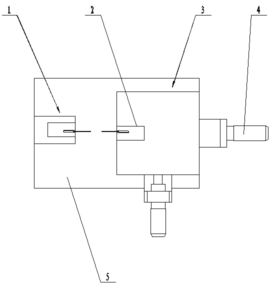
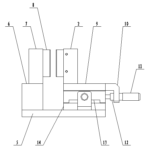
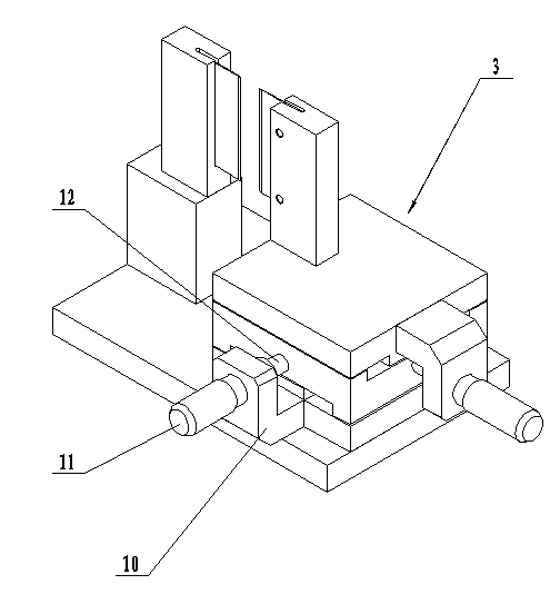
[0015] like Figure 1 to Figure 3 As shown, an optical fiber stripping device includes two parallel-installed cutter assemblies 1, a height block 6, a slide table 3 and a base 5,. The cutter assembly 1 includes a wire stripping blade 8 and a knife holder. The two stripping blades 8 are respectively installed on the left and right relative fixed knife rest 7 and the movable knife rest 2, wherein the fixed knife rest 7 is installed on the height block 6, and the height block 6 is installed on the base 5, which is placed on the left side of the base The position on the side; the movable knife rest 2 is installed on the top layer 9 of the slide table 3, and the slide table 3 is placed on the right side of the base.

[0016] The slide table 3 includes a bottom layer 14 , a middle layer 13 and a top layer 9 connected from bottom to top. The b...


PUM


Abstract

The invention discloses an optical fiber stripping device, which comprises two stripping blades which are arranged side by side, wherein the stripping blades are respectively arranged on a fixed cutter rack and a movable cutter rack which are arranged oppositely on the left and the right; the fixed cutter rack is connected to a height block; the height block is arranged on a base; and the movable cutter rack is arranged on the top of a sliding table. When an optical fiber is stripped, the position of the movable cutter rack is adjusted such that a distance between the two blades is equal to a diameter of a bushing, then the optical fiber slides from top to bottom along a gap between the two blades, and the optical fiber is slightly rotated. The hardness of a rubber skin is much smaller than that of a Kelvar wire doped in the bushing, so that the rubber skin is cut off by the blades in the process that the optical fiber slides down, while the bushing and the Kelvar wire cannot be damaged. In the whole process, time and labor are saved, the stripping quality can be guaranteed, a phenomenon that a worker is injured due to careless operation can be avoided, and a cut of the rubber skin is flat and looks beautiful.

Description

technical field [0001] The invention relates to the field of optical fiber stripping, in particular to an optical fiber stripping device. Background technique [0002] An optical fiber is a light-conducting element that utilizes the principle of total reflection of light in fibers made of glass or plastic. The optical fiber has strong information transmission ability and strong anti-interference ability, but the inner fiber is very thin and the strength is poor. Therefore, in actual use, it is necessary to wrap the sleeve on the outside of the optical fiber and mix it with Kevlar wire to increase the strength. In addition, it must be wrapped A layer of rubber skin to prevent the casing from being worn. [0003] In some occasions, the rubber sheath of the optical fiber needs to be stripped off, leaving the sleeve and the optical fiber wrapped in the sleeve. For example, when producing an optical fiber with an adapter, the outermost layer of rubber is removed from the part w...

Claims


Application Information

Patent Timeline
IPC IPC(8): G02B6/245
Inventor 刘凌益
Owner 无锡爱沃富光电科技有限公司
Learn More