
Touch device and touch display device

A touch display device, touch device technology, applied in the direction of instrument, electrical digital data processing, input/output process of data processing, etc. The effect of reliability and low light leakage rate

Inactive Publication Date: 2012-11-28
WINTEK CORP
View PDF6 Cites 22 Cited by
  • Summary
  • Abstract
  • Description
  • Claims
  • Application Information

AI Technical Summary

Problems solved by technology

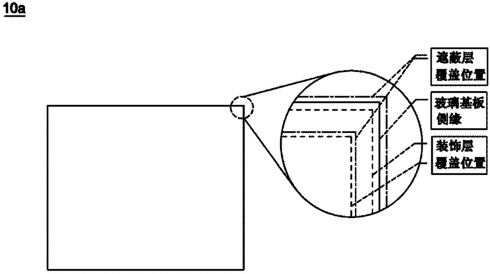
[0003] like Image 6 In the existing design, without any protection, the frame of a traces on lens is prone to problems such as reliability or scratches
Furthermore, since the designs of cover lenses on the market are very diverse, special-shaped edging processing is required to obtain the desired shape. However, special-shaped edging processing can easily lead to serious edge exposure problems

Method used


Image

  • Touch device and touch display device
  • Touch device and touch display device
  • Touch device and touch display device

Examples


Embodiment Construction

[0061] Other purposes and advantages of the present invention can be further understood from the technical features disclosed in the present invention. In order to make the above and other objects, features and advantages of the present invention more comprehensible, the following specific embodiments are described in detail with reference to the accompanying drawings.

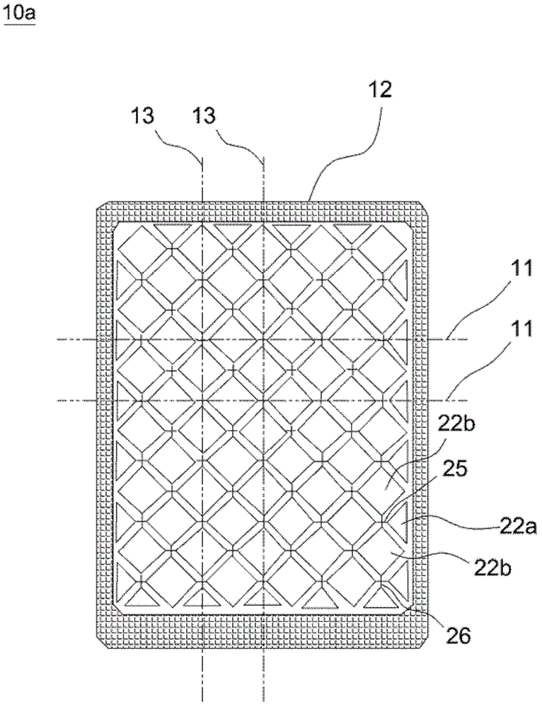
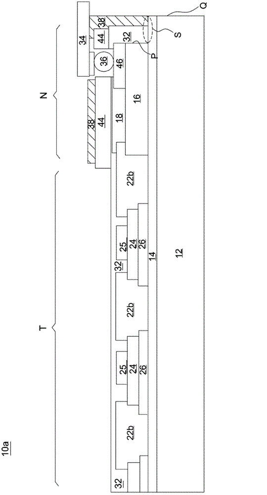
[0062] figure 1 is a schematic plan view of a touch device according to an embodiment of the present invention, figure 2 for figure 1 The enlarged schematic diagram of the cross-section. Please also refer to figure 1 and figure 2 , the touch device 10a according to an embodiment of the present invention is composed of a transparent substrate 12 and a laminated structure formed on the transparent substrate 12, and the touch device 10a can be divided into a touch operation area T and a non-touch Control area N. In this embodiment, the non-touch area N is located around the touch device 10a and surroun...


PUM


Abstract

The invention provides a touch device and a touch display device. The touch device comprises a transparent substrate, a touch sensing structure, a decorative layer, a routing layer, a protective layer and a shielding layer, wherein the decorative layer is arranged on the transparent substrate and is located in a non-contact area; and the routing layer is arranged on the decorative layer, the protective layer is arranged on the transparent substrate and at least covers the touch sensing structure and the routing layer, and the shielding layer is at least arranged on the protective layer and is located in the non-contact area.

Description

technical field [0001] The touch technology of the present invention is particularly related to a touch device with high reliability and low light leakage rate. Background technique [0002] Such as Image 6 As shown, an existing touch device 100 has a glass substrate 102, a silicide insulating layer 104 formed on the glass substrate 102, a plurality of touch sensing electrodes (such as X-axis electrodes 106a and Y-axis electrodes 106b), The wiring layer 108 , the organic insulating layer 110 and the decoration layer 112 . The X-axis electrodes 106a and the Y-axis electrodes 106b, for example, can be arranged along two directions perpendicular to each other. The shaft electrodes 106b may be connected to each other by electrode connection pads 114 . The wiring layer 108 includes a plurality of metal wirings, and a silicide insulating layer 116 completely covers the X-axis electrode 106a, the Y-axis electrode 106b, the wiring layer 108, etc. as a protection layer. [0003] ...

Claims


Application Information

Patent Timeline
Patent Type & Authority Applications(China)
IPC IPC(8): G06F3/041
Inventor 吴明坤苏国彰陈佳琪林於亭
Owner WINTEK CORP
Learn More