Image splicing method and device based on linear array camera shooting

A linear array camera and image stitching technology, applied in the field of image processing, can solve the problems of large amount of offset calculation, large image overlap position, slow image stitching, etc.

Active Publication Date: 2012-11-28
KONFOONG BIOTECH INT
View PDF4 Cites 18 Cited by
  • Summary
  • Abstract
  • Description
  • Claims
  • Application Information

AI Technical Summary

Problems solved by technology

[0005] The technical solution of the present invention is to solve the problem that in the prior art, due to the relatively large overlapping positions between the images, the amount of calculation of the corresponding offset is also relatively large, which causes the problem that the image splicing in the prior art is slow

Method used


Image

  • Image splicing method and device based on linear array camera shooting
  • Image splicing method and device based on linear array camera shooting
  • Image splicing method and device based on linear array camera shooting

Examples


Embodiment 1

[0043] Combine below figure 2 with image 3 The image stitching method based on the line scan camera shooting of this embodiment will be described in detail.

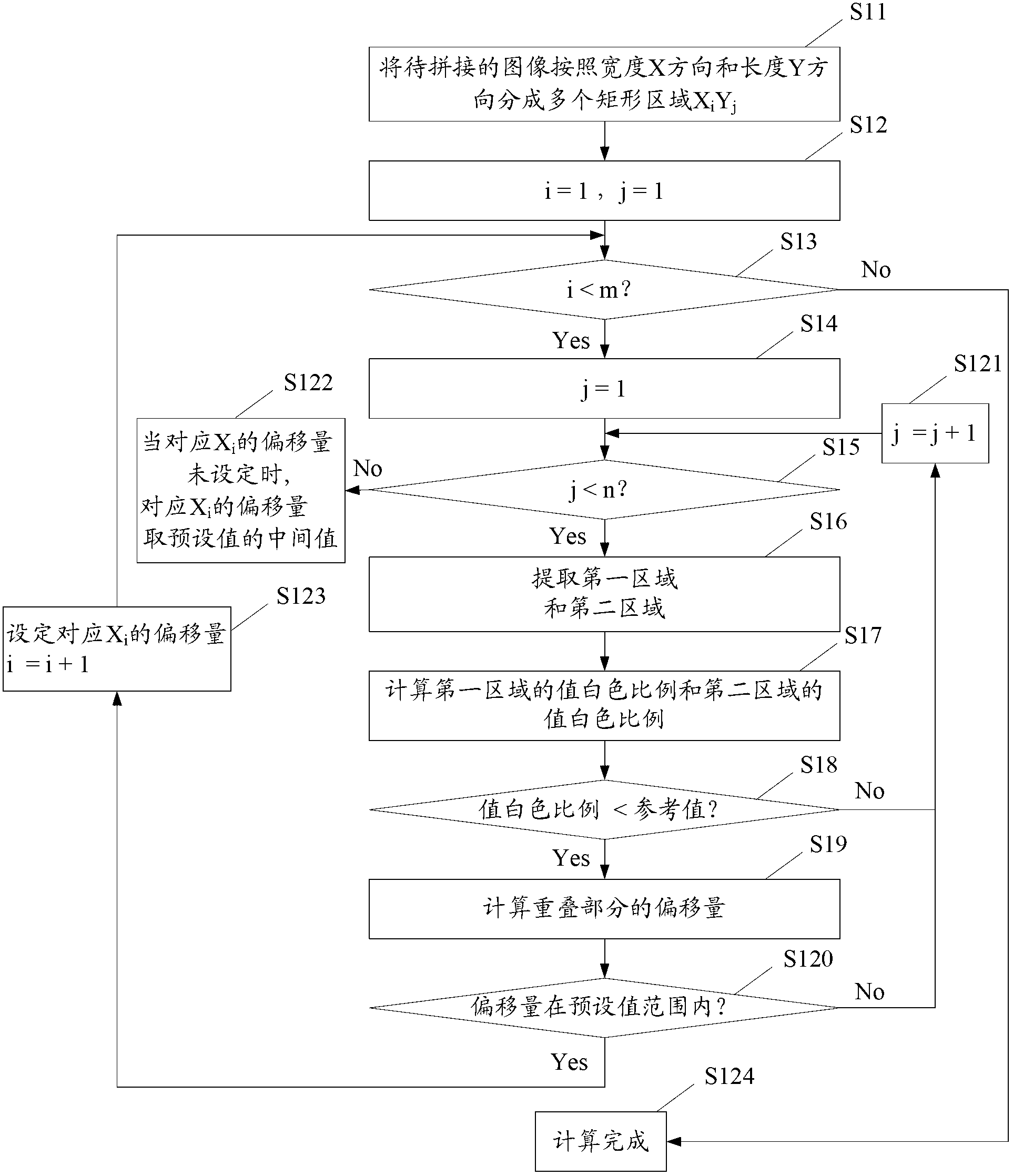
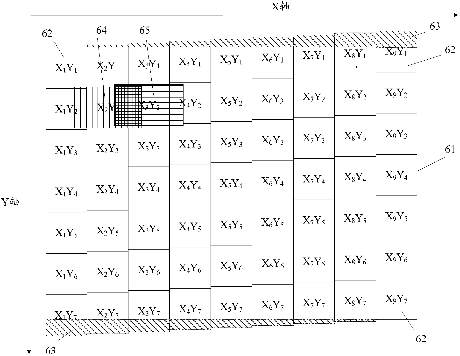
[0044] figure 2 It is a schematic flow chart of an image stitching method based on a line array camera in an embodiment of the present invention. According to the diagram, step S11 is first performed, and the image to be stitched is divided into multiple rectangular areas according to the width X direction and length Y direction, wherein the X direction is the splicing direction, i=1~m, j=1~n.

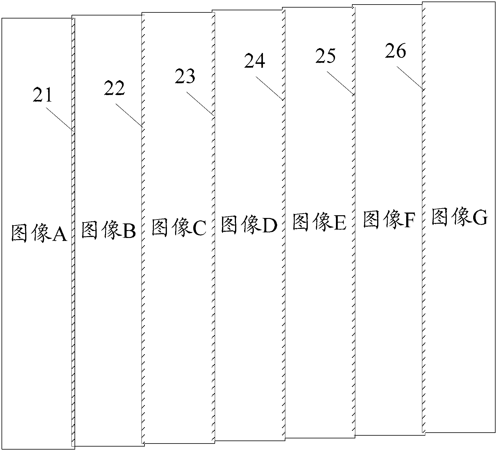
[0045] image 3 It is a schematic diagram of the image partitions to be stitched in the image stitching method based on the line-scan camera shooting in the embodiment of the present invention, as image 3 As shown, the image 61 to be stitched is stitched along the X direction, the image 61 to be stitched is divided into a plurality of rectangular areas 62, and the rectangular areas 62 are respectively named according to t...

Embodiment 2

[0067] Figure 5 It is a schematic flowchart of the image stitching method captured by the line scan camera in this embodiment. For the detailed steps of the specific splicing method, refer to Embodiment 1. The difference from Embodiment 1 is that after step S16 is executed, step S17 is omitted to calculate the value white ratio of the first region and the value white ratio of the second region, and step S18 is used to determine the value white ratio. In the two steps of whether the ratio is smaller than the reference value, step S16 extracts the first area and the second area and then proceeds directly to step S19 to calculate the offset of the overlapping portion.

[0068] Based on the above-mentioned image stitching method taken by the line array camera, this embodiment also provides an image stitching device taken by the line array camera. The structural diagram of the device is as follows Image 6 shown, including:

[0069] Blocking unit 81, for dividing the image to be...


PUM


Abstract

The invention discloses an image splicing method and device based on linear array camera shooting. The method comprises the following steps: dividing a image to be spliced into multiple rectangular areas XiYj according to the width X direction and length Y direction, wherein the X direction is the splicing direction, i=1 to m, and j=1 to n; setting the initial values of i and j as 1; calculating the offset of the overlapped part between the area XiYj and the area X(i+1)Yj; judging whether the calculated offset is in a preset range; if so, setting the calculated offset as the offset of corresponding Xi, and setting i=i+1 and j=1; otherwise, setting j=j+1; repeating the calculating and judging steps until i=m or j=n; and finishing the splicing operation according to the offset of corresponding Xi. When in image splicing based on linear array camera shooting, the technical scheme of the invention reduces the area of the part needing calculation by dividing the overlapped part and calculating the offset, thereby increasing the splicing speed.

Description

technical field [0001] The present invention relates to the technical field of image processing, in particular to an image splicing method and device based on a line scan camera. Background technique [0002] With the large-scale popularization of machine vision and the improvement of the speed and precision of industrial assembly lines, line scanning systems are increasingly recognized by vision engineers and end users. Since the linear array CCD (Charge Coupled Device) device in the line scan system has the characteristics of high spatial resolution and can realize high-precision measurement, the use of linear array CCD for non-contact one-dimensional measurement has been widely used. With the need for scanning imaging cost control, the requirement for clear imaging of complex target surfaces, and the improvement of the positioning accuracy of fine mobile platforms, line scan cameras are widely used to scan and shoot specified target surfaces. The existing technology that...

Claims


Application Information

Patent Timeline
Patent Type & Authority Applications(China)
IPC IPC(8): G06T5/50
Inventor 刘炳宪谢菊元王炎辉陈丽桥
Owner KONFOONG BIOTECH INT
Why Eureka
Try Eureka