Busway shell

A technology of bus duct and housing, applied in the field of bus duct housing, can solve the problems such as the heat dissipation structure does not play a role in heat dissipation, the heat dissipation effect of the bus duct housing is reduced, and the reliability of the product is reduced, so as to improve the heat dissipation effect and the heat dissipation effect. Good, improve the effect of strength and stiffness

Inactive Publication Date: 2012-11-28
广州市半径电力铜材有限公司
View PDF5 Cites 5 Cited by
  • Summary
  • Abstract
  • Description
  • Claims
  • Application Information

AI Technical Summary

Problems solved by technology

[0003] As far as the existing busway shell is concerned, most of the heat transferred by the busbar is concentrated on the side plates, and a small part is transmitted outward through the upper and lower plates, and the heat dissipation effect is poor; a new type of busway has appeared later The shell has a heat dissipation structure added to the side plate. In practical applicati...

Method used


Image

  • Busway shell
  • Busway shell
  • Busway shell

Examples


Embodiment 1

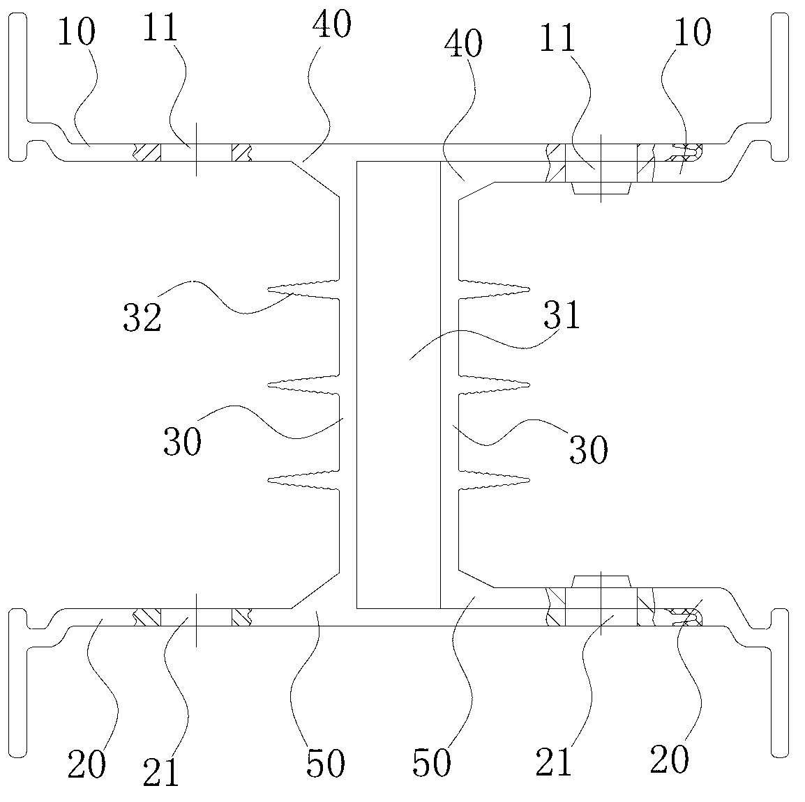
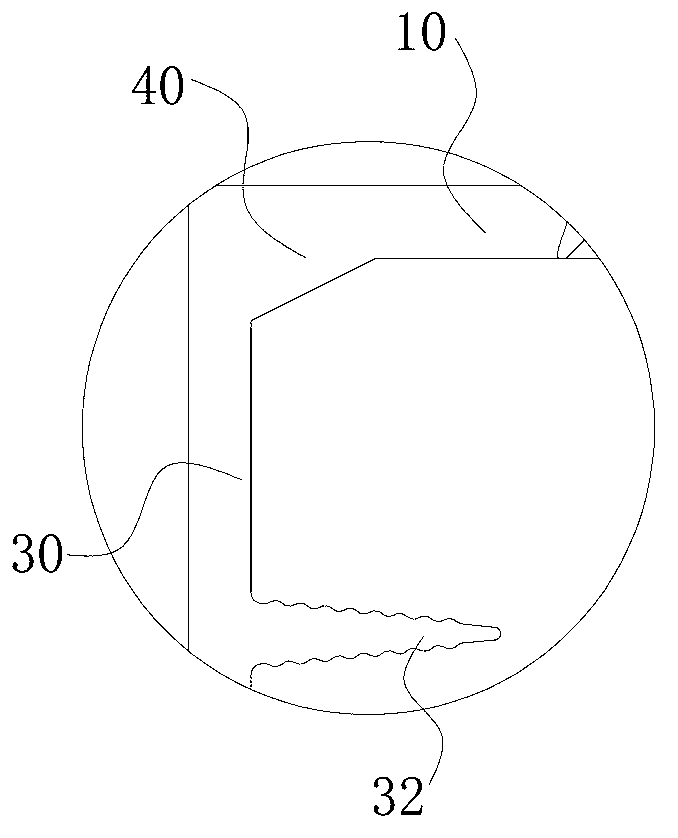
[0037] Such as Figure 1 to Figure 5 As shown, a busway housing includes two upper plates 10, two lower plates 20 and two side plates 30, the two side plates 30 are located between the upper plate 10 and the lower plate 20, and the two side plates 30 forms a bus bar placement position 31, the area between the upper plate 10 and the lower plate 20 is a heat dissipation area, the upper convection holes 11 are provided on the two upper plates 10, and the lower convection holes 21 are provided on the lower plates 20, The upper convection hole 11 is located above the heat dissipation area, and the lower convection hole 21 is located below the heat dissipation area.

[0038] Among them, the bus duct housing includes an "I" shape and a "C" shape. The cross section of the "I" shape is "I" shape, and the cross section of the "C" shape is "C" shape; the "C" shape is snapped into the In the "worker" shape, a pair of upper plates 10 and lower plates 20 are respectively located at the upp...

Embodiment 2

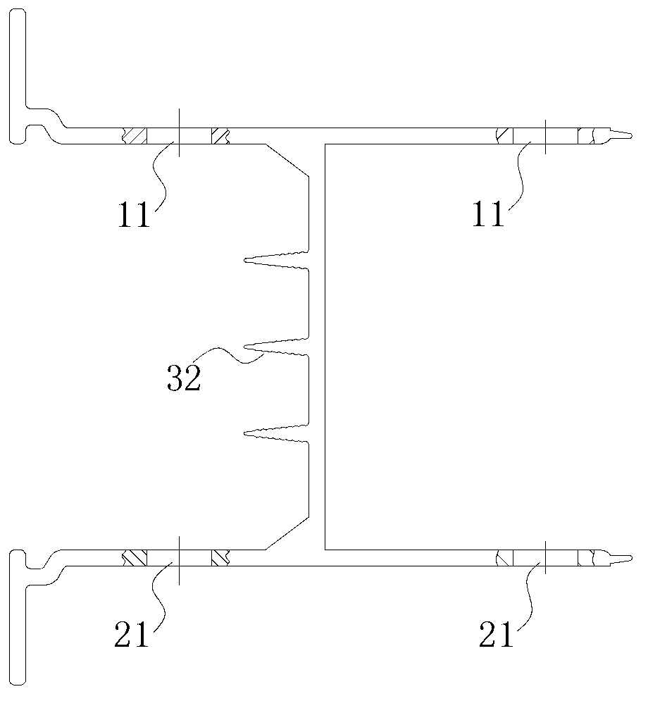
[0047] Such as Image 6 , Figure 7 As shown, the difference between this embodiment and Embodiment 1 is that, in order to avoid the appearance of "quilt effect", the method adopted in this embodiment is: the height of the heat dissipation protrusion 32 is 3 mm to 5 mm (preferably 4 mm), and the distance between two adjacent heat dissipation protrusions 32 is 4 mm to 8 mm (preferably 6 mm).


PUM

PropertyMeasurementUnit
Heightaaaaaaaaaa
Heightaaaaaaaaaa

Abstract

The invention discloses a busway shell comprising two upper plates, two lower plates and two side plates, wherein the two side plates are located between the upper plates and the lower plates; a bus laying position is formed between the two side plates; a region formed between each upper plate and each lower plate is a heat radiating region; the two upper plates are provided with upper convection holes; the lower plates are provided with lower convection holes; the upper convection holes are located above the heat radiating regions; and the lower convection holes are located below the heat radiating regions. By using the busway shell, the heat radiating effect of the busway shell can be improved, the reliability of the busway shell can be improved, and the service life of the busway shell can be prolonged.

Description

technical field [0001] The invention relates to a bus duct housing. Background technique [0002] The busway housing forms a busbar placement position for placing the busbar. During use, a large amount of heat will be generated. The existing busway housing includes an upper plate, a lower plate and a side plate. The heat transferred by the busbar is transferred to A part of the heat is transferred outwards through the side plates, and another part of the heat is transferred to the upper plate and the lower plate through the side plates, and then transferred outwards from the upper plate and the lower plate. [0003] As far as the existing busway shell is concerned, most of the heat transferred by the busbar is concentrated on the side plates, and a small part is transmitted outward through the upper and lower plates, and the heat dissipation effect is poor; a new type of busway has appeared later The shell has a heat dissipation structure added to the side plate. In practic...

Claims


Application Information

Patent Timeline
IPC IPC(8): H02G5/04H02G5/10
Inventor 郑旭飞陈庆周夏超
Owner 广州市半径电力铜材有限公司
Why Eureka
Try Eureka