Rotary piezoelectric generator for rail vehicle shafting monitoring system
- Summary
- Abstract
- Description
- Claims
- Application Information
AI Technical Summary
Problems solved by technology
Method used
Image
Examples
Embodiment Construction
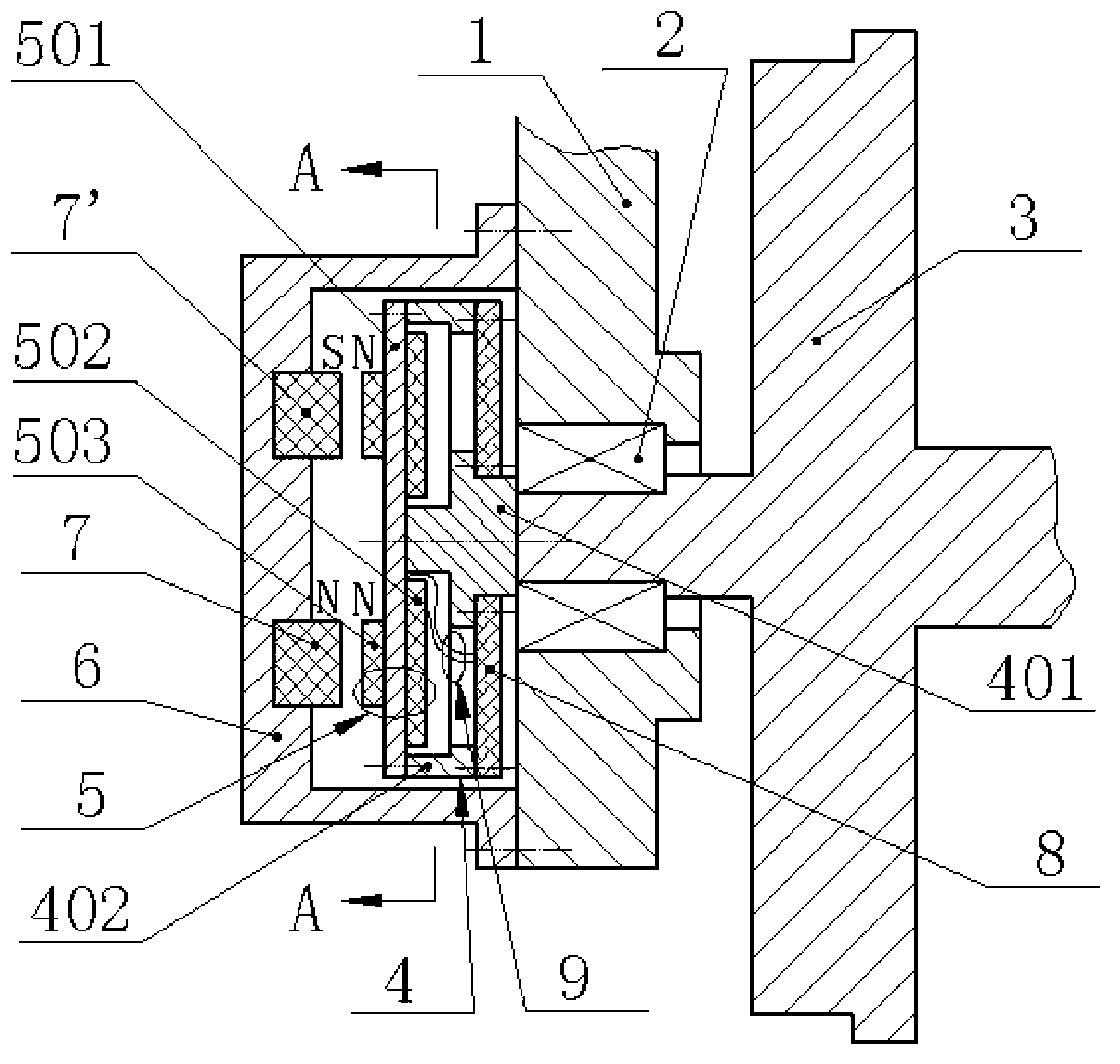
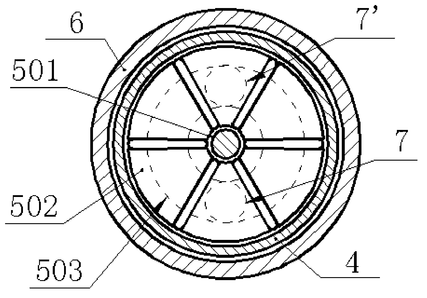
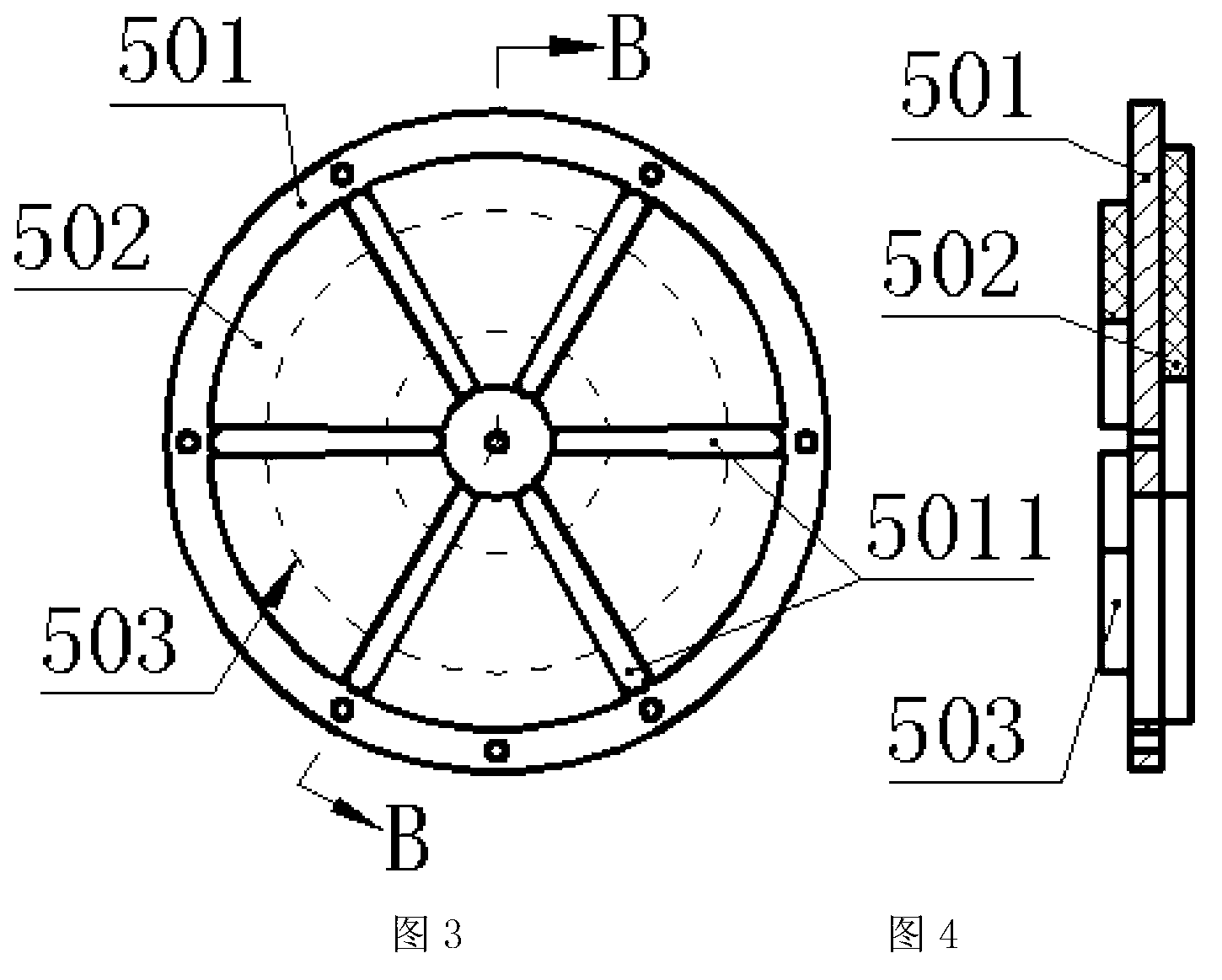
[0015] The wheel shaft 3 is installed on the vehicle frame 1 through the bearing 2; the small end 401 of the T-block 4 is mounted on the end of the wheel shaft 3 through screws and pressed on the inner ring of the bearing 2, and the two sides of the big end 402 are respectively connected by screws. A piezoelectric transducer 5 and a sensor monitoring system 8 are installed, and the piezoelectric transducer 5 and the sensor monitoring system 8 are connected by a wire group 9; the piezoelectric transducer 5 is composed of a circular metal substrate 501, The fan-shaped piezoelectric chip 502 and the fan-shaped magnetic sheet 503 are bonded together, and the circular metal substrate 501 is provided with evenly distributed radial narrow grooves 5011; the bearing cap 6 is installed on the vehicle frame 1 by screws, and the bearing cap The inner bottom of 6 is inlaid with a first fixed magnet 7 and a second fixed magnet 7'; the magnetic poles of the first fixed magnet 7 and the second...
PUM
 Abstract
Description
Claims
Application Information
 - R&D
- Intellectual Property
- Life Sciences
- Materials
- Tech Scout
- Unparalleled Data Quality
- Higher Quality Content
- 60% Fewer Hallucinations
Browse by: Latest US Patents, China's latest patents, Technical Efficacy Thesaurus, Application Domain, Technology Topic, Popular Technical Reports.
© 2025 PatSnap. All rights reserved.Legal|Privacy policy|Modern Slavery Act Transparency Statement|Sitemap|About US| Contact US: help@patsnap.com


