A Rotationally Excited Oscillating Friction-Piezoelectric Generator

A generator and swing technology, applied in the direction of friction generators, generators/motors, piezoelectric effect/electrostrictive or magnetostrictive motors, etc., can solve friction, wear and vibration between friction pairs of sliding friction generators Low adaptability to frequency and rotating body speed, low power generation capacity and energy density per unit volume, etc., to achieve strong speed adaptability, avoid excessive deformation and damage, and simple structure and excitation process

Active Publication Date: 2021-10-08
ZHEJIANG NORMAL UNIVERSITY
View PDF0 Cites 0 Cited by
  • Summary
  • Abstract
  • Description
  • Claims
  • Application Information

AI Technical Summary

Problems solved by technology

From the perspective of practical application, various types of generators currently proposed still face many technical bottlenecks. The common problems are summarized as follows: ① low power generation capacity and energy density per unit volume; Low adaptability to flow velocity, vibration frequency and rotating body speed, ③low reliability, such as piezoelectric ceramics are easily damaged due to excessive environmental vibration intensity, and sliding friction generators are easy to fail due to friction and wear between friction pairs. ④There is electromagnetic interference , such as electromagnetic generators, nonlinear piezoelectric and friction generators based on magnetic coupling auxiliary excitation, there is a certain magnetic field when they work
Of course, it is still difficult to solve all the above-mentioned problems in the same generator
The common feature of pure piezoelectric generators and friction generators is that they have no electromagnetic interference, so they are more suitable for wireless sensor monitoring systems, and their respective power generation capabilities, reliability and environmental adaptability need to be further improved

Method used


Image

  • A Rotationally Excited Oscillating Friction-Piezoelectric Generator
  • A Rotationally Excited Oscillating Friction-Piezoelectric Generator
  • A Rotationally Excited Oscillating Friction-Piezoelectric Generator

Examples


Embodiment Construction

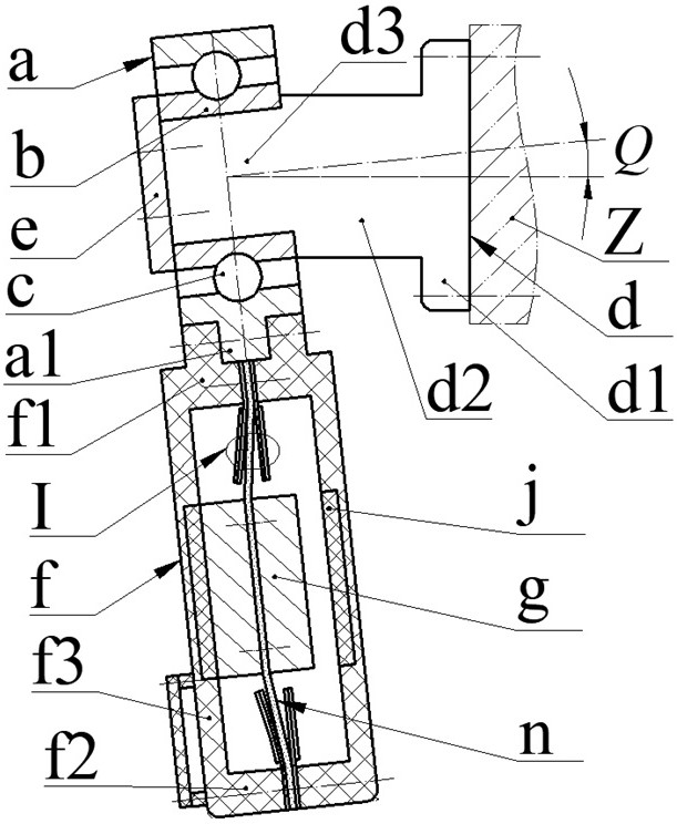
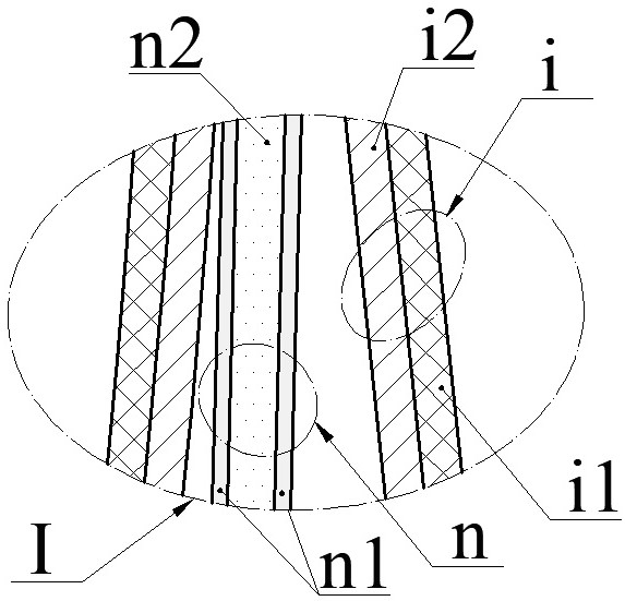
[0020] The generator proposed in the present invention mainly comprises a swing ring a, ring fixed b, the rolling element c, the shaft d, composite beam n, i, and the piezoelectric vibrator housing f. Shaft d, spindle and a minor axis d2 d3 is constituted by a flange d1, d2 right end of the shaft is provided with a spindle d flange d1, the left end of the counter shaft provided d3, fixed ring b through e, and the screw bracket is mounted on the counter shaft d3, a swing ring via the rolling bodies on a given turn sets c b, c rolling body is a ball or a cylinder; swing angle of the main axis of the coil axis x1 and x2 in the same plane as the axis angle Q, the coil axis x2 pendulum swing ring means and a inner bore axis coinciding with the axis of the outer cylindrical ring and the constant c b turning centerline of the rolling element; d3 when the countershaft is oblique axis, the angle between the secondary shaft and the spindle d2 d3 in the same plane as the axis angle Q , swing...


PUM


Abstract

The invention relates to a rotationally excited swing friction-piezoelectric generator, which belongs to the technical field of new energy sources. It mainly includes swing ring, fixed ring, rolling body, rotating shaft, composite beam, piezoelectric vibrator and shell: the left end of the main shaft of the rotating shaft is provided with a sub-shaft, the fixed ring is installed on the auxiliary shaft, and the swing ring is sleeved on the fixed ring; the main axis and The included angle between the axes of the pendulum ring in the same plane is the axial inclination angle. There are shells on both sides of the bump on the outer edge of the pendulum ring. The two ends of a composite beam and one end of two pairs of piezoelectric vibrators are crimped on the two shells. Between the upper bottom wall or the lower bottom wall of the body, the piezoelectric vibrator is located on both sides of the composite beam; the composite beam is composed of the beam substrate and the friction layers on both sides, and the piezoelectric vibrator is composed of the piezoelectric vibrator bonded to the vibrator substrate and one side. The vibrator substrate is installed close to the friction layer of the composite beam; the inertia blocks are installed on both sides of the middle of the composite beam, and the center of the side wall of the shell is inlaid with a buffer pad; the vibrator substrate and the piezoelectric sheet constitute a piezoelectric power generation unit, and the vibrator substrate And the composite beam constitutes a friction power generation unit.

Description

Technical field [0001] The present invention belongs to the technical field of new energy and energy recovery, particularly relates to a rotary oscillating excitation friction - piezoelectric generator, for collecting fluid energy turbine generator and a rotation shaft. Background technique [0002] In recent years, real-time health sensing techniques for high-rise buildings, bridges, large and high-speed rotating machines have been widely used. In addition, monitoring of river water quality pollution, flood prevention and warning and atmospheric pollution has been attached importance to the relevant state departments, and domestic experts and scholars have proposed corresponding monitoring methods and means, such as water quality monitoring technology for river water pollution, for flooding And the rainstorm, water level and river water flow rate of natural disasters such as mudslides. At the same time, in order to realize self-powered and maintenance of various monitoring syste...

Claims


Application Information

Patent Timeline
Patent Type & Authority Patents(China)
IPC IPC(8): H02N2/18H02N1/04
CPCH02N1/04H02N2/185H02N2/186
Inventor 阚君武张李寇福兵王淑云曹红兵龙蛟曾平吴鸣
Owner ZHEJIANG NORMAL UNIVERSITY
Why Eureka
Try Eureka