Orthogonal signal quadruplicated frequency counting method with filter function

A quadrature signal, counting method technology, applied in electrical components, pulse technology and other directions, can solve the problems of counting errors, interference, lack of filtering function, etc., to overcome the loss of counting and shield electromagnetic interference.

Inactive Publication Date: 2012-11-28
HARBIN INST OF TECH
View PDF1 Cites 6 Cited by
  • Summary
  • Abstract
  • Description
  • Claims
  • Application Information

AI Technical Summary

Problems solved by technology

[0003] The purpose of the present invention is to solve the problem that the current technical method lacks the filter function and easily introduces glitch interference, resulting in counting errors. The present invention provides a quadrature signal quadruple frequency counting method with a filter function

Method used


Image

  • Orthogonal signal quadruplicated frequency counting method with filter function
  • Orthogonal signal quadruplicated frequency counting method with filter function

Examples


specific Embodiment approach 1

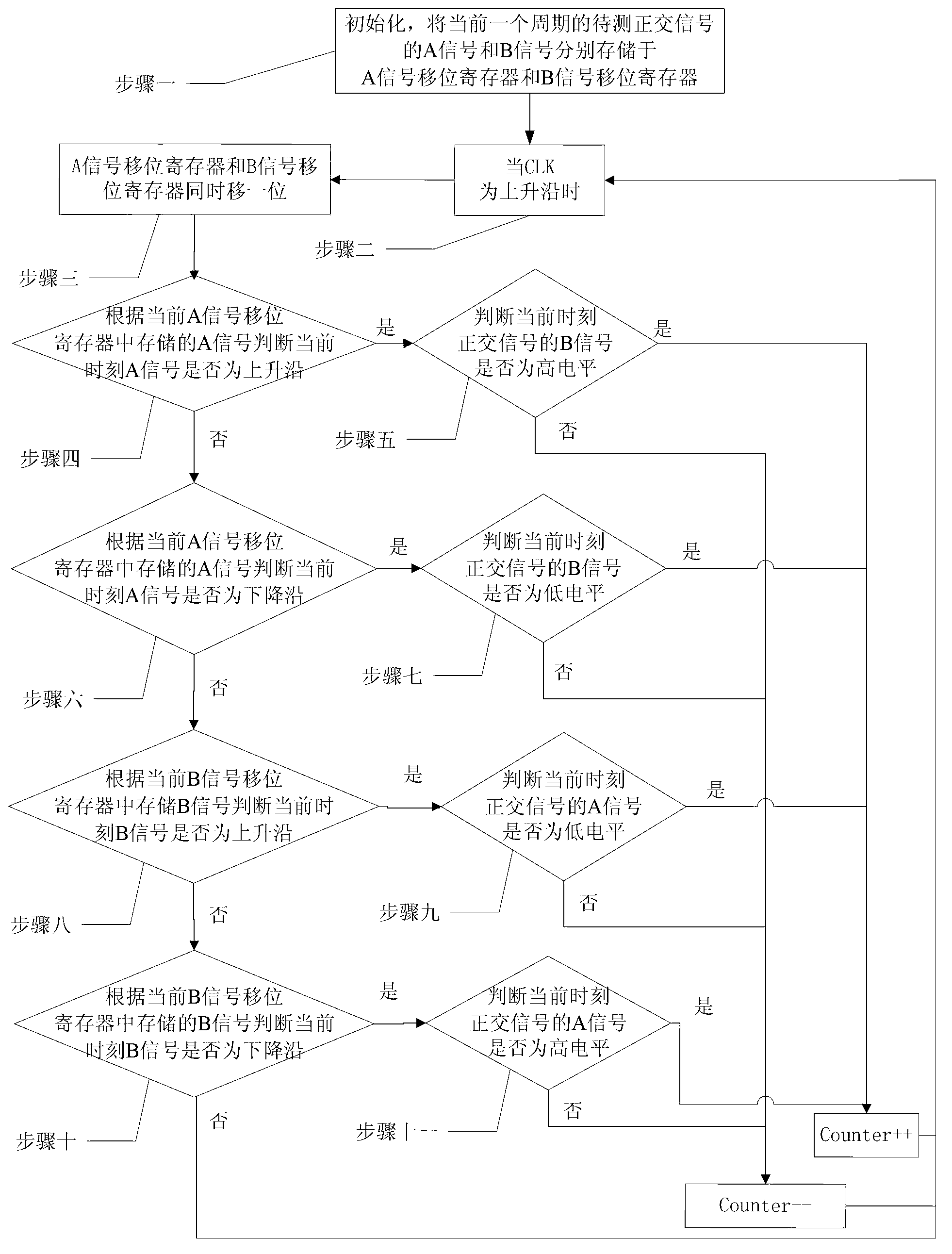
[0019] Specific implementation mode one: combine figure 1 Describe the present embodiment, the quadrature signal quadruple frequency counting method with filtering function described in the present embodiment, it comprises the steps:

[0020] Step 1: Initialize the counter, the A signal shift register and the B signal shift register. The storage spaces of the A signal shift register and the B signal shift register are both 4 bits, and the A signal shift register is used to store a cycle The A signal in the quadrature signal, the B signal shift register is used to store the B signal in the quadrature signal of one cycle;

[0021] Step 2: When the clock signal CLK is rising, go to Step 3;

[0022] Step 3: The A signal shift register and the B signal shift register shift one bit at the same time, and go to step 4;

[0023] Step 4: According to the A signal of one period stored in the current A signal shift register, it is judged whether the A signal is a rising edge at the curr...

specific Embodiment approach 2

[0034] Specific embodiment two: this embodiment is a further limitation of the quadrature frequency counting method for quadrature signals with filtering function described in specific embodiment one,

[0035] In step 4, the method of judging whether the A signal at the current moment is a rising edge according to the A signal of one cycle stored in the current A signal shift register is: if the A signal of one cycle stored in the A signal shift register is 0011, then It is judged that the A signal is a rising edge, and if not, it is judged that the A signal is not a rising edge.

specific Embodiment approach 3

[0036] Specific embodiment three: this embodiment is a further limitation of the quadrature frequency counting method for quadrature signals with filtering function described in specific embodiment one,

[0037] In step 6, the method of judging whether the A signal at the current moment is a falling edge according to the A signal of one cycle stored in the current A signal shift register is: if the A signal of one cycle stored in the A signal shift register is 1100, then It is judged that the A signal is a falling edge, and if not, it is judged that the A signal is not a falling edge.


PUM


Abstract

The invention relates to an orthogonal signal quadruplicated frequency counting method with a filter function, and relates to an orthogonal signal quadruplicated frequency counting method. The invention aims at solving the problem of the prior art that counting mistake is caused by interference of burrs which are easily introduced by shortage of a filter function. A counter, a signal shifting register A and a signal shifting register B are initialized, the signal shifting register A and the signal shifting register B are shifted for one bit at each clock edge, and values stored in the signal shifting register A and the signal shifting register B are used for analyzing whether the edge of a signal A or a signal B exists or not. If the edge of the signal A or the signal B exists, the level of another phase of signal is detected according to the edge of the current signal A or the signal B so as to judge the steering of a motor; when the motor rotates in reverse, the counter is minus one; and when the motor rotates normally, the counter is plus one and waits for a next clock. The method is used for counting the orthogonal signal quadruplicated frequency.

Description

technical field [0001] The invention relates to a quadrature frequency counting method for quadrature signals, in particular to a quadrature signal quadruple frequency counting method with filtering function. Background technique [0002] The quadrature signal multiplier counters with quadrature signals commonly used in the existing comparison flow often have counting loss and hysteresis when the motor commutates, and they do not have a filtering function at the same time. In actual work, the loss and lag of counting will affect the control accuracy of the system. At the same time, when the motor keeps reversing back and forth, it may cause error accumulation. After a long time, the system will lose accuracy; Burrs on the falling edge are very common on some domestic code discs & scales. Counters without filtering function can easily introduce glitch interference, resulting in counting errors. Contents of the invention [0003] The purpose of the present invention is to s...

Claims


Application Information

Patent Timeline
Patent Type & Authority Applications(China)
IPC IPC(8): H03K21/00
Inventor 高会军吴志兵孙一勇孙光辉任雨卫作龙卢秋刚周世亮
Owner HARBIN INST OF TECH
Why Eureka
Try Eureka