

Analog anti-vibration crystal oscillator compensation device and method
A technology of crystal oscillators and compensation devices, applied in power oscillators, electrical components, etc., can solve the problems of low AVXO accuracy and achieve the effects of simple compensation structure, simple compensation process, easy integration and mass production
- Summary
- Abstract
- Description
- Claims
- Application Information
AI Technical Summary
Problems solved by technology
Method used
Image

Examples
Embodiment 1
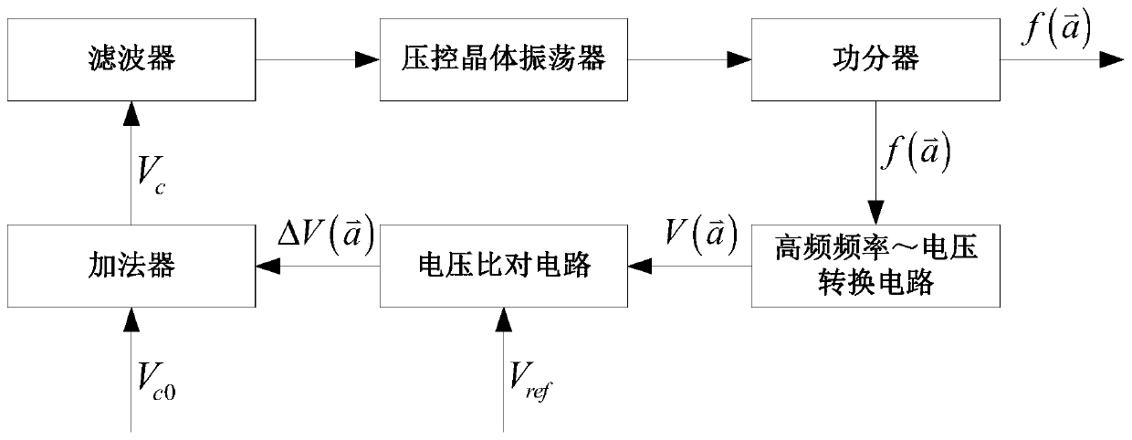
[0043] An embodiment of the present invention provides an analog anti-vibration crystal oscillator compensation device, such as figure 1 As shown, it includes a voltage-controlled crystal oscillator, a power divider, a high-frequency frequency-to-voltage conversion circuit, a voltage comparison circuit, an adder and a filter that are connected in sequence to form a closed-loop structure.
[0044] The voltage-controlled crystal oscillator is used to generate a stable oscillation frequency signal and output it to the power divider.
[0045] The power divider is used to divide the output signal of the voltage-controlled crystal oscillator into two channels, one of which is used as the output signal of the analog anti-vibration crystal oscillator compensation device, and the other is output to the high-frequency frequency-voltage conversion circuit.
[0046] The high-frequency frequency-to-voltage conversion circuit is used to collect the nominal frequency f of the voltage-control...
Embodiment 2
[0055] An embodiment of the present invention provides an analog anti-vibration crystal oscillator compensation method, such as Figure 5 As shown, the following steps S1-S7 are included:
[0056] S1. Under non-vibration conditions, apply a voltage control voltage V to the voltage control terminal of the voltage-controlled crystal oscillator c0 , so that it outputs the nominal frequency f 0 , and through the high-frequency frequency to voltage conversion circuit, the nominal frequency f 0 converted to the reference voltage V ref .
[0057] S2. Under vibration conditions, the real-time output frequency of the voltage-controlled crystal oscillator is divided by the power divider It is divided into two circuits, one of which is used as the output signal of the analog anti-vibration crystal oscillator compensation device, and the other is output to the high-frequency frequency-voltage conversion circuit.
[0058] S3, through the high-frequency frequency to voltage conversion...
PUM
 Abstract
Description
Claims
Application Information