A Digital Temperature Compensation Method for Crystal Oscillator

A technology of digital temperature compensation and crystal oscillator, applied in the direction of electrical components, output stability, etc., can solve the problems of temperature sensor and resonant chip temperature hysteresis, limited compensation accuracy, failure to make breakthroughs, etc., to achieve easy integration and mass production, Good compensation effect, easy real-time high-precision compensation effect

Active Publication Date: 2021-01-26
UNIV OF ELECTRONICS SCI & TECH OF CHINA
View PDF2 Cites 0 Cited by
  • Summary
  • Abstract
  • Description
  • Claims
  • Application Information

AI Technical Summary

Problems solved by technology

This method has advantages in phase noise characteristics when realizing high-frequency temperature-compensated crystal oscillators (TCXO), but the composition is relatively complicated and has not been widely used yet.
[0016] In summary, the existing temperature compensation methods for crystal oscillators all adopt an open-loop compensation framework, and a temperature sensor is used. The temperature sensor is as close as possible to the crystal resonator on the circuit, and the resonator chip of the crystal resonator It is packaged separately in a closed space, which inevitably produces a temperature hysteresis between the temperature sensor and the resonant chip, resulting in a failure to achieve a breakthrough in the frequency-temperature characteristics of the temperature-compensated crystal oscillator, that is, the TCXO.
Especially for crystal oscillators whose output signals are high frequency, this temperature hysteresis problem is more serious, and the compensation accuracy is limited

Method used


Image

  • A Digital Temperature Compensation Method for Crystal Oscillator
  • A Digital Temperature Compensation Method for Crystal Oscillator
  • A Digital Temperature Compensation Method for Crystal Oscillator

Examples


Embodiment Construction

[0039] Specific embodiments of the present invention will be described below in conjunction with the accompanying drawings, so that those skilled in the art can better understand the present invention. It should be noted that in the following description, when detailed descriptions of known functions and designs may dilute the main content of the present invention, these descriptions will be omitted here.

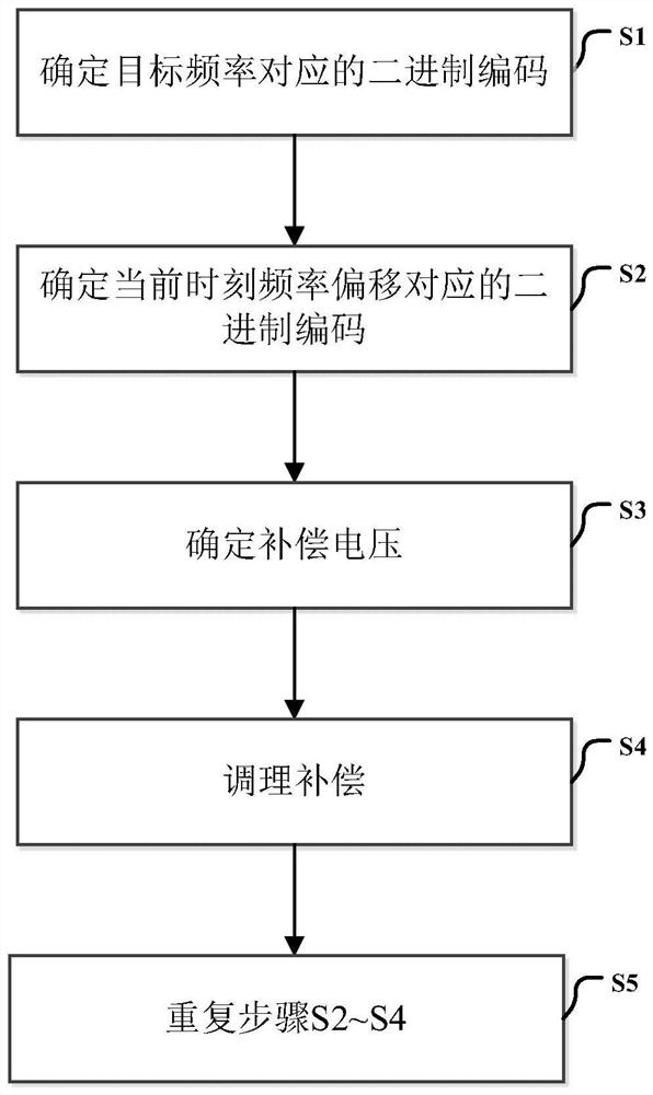
[0040] image 3 It is a specific implementation flowchart of the digital temperature compensation method of the crystal oscillator of the present invention.

[0041] In this example, if image 3 As shown, the digital temperature compensation method of the crystal oscillator of the present invention comprises the following steps:

[0042] Step S1: Determine the target frequency f 0 Corresponding binary code B 0i

[0043] at room temperature T 0 , such as at 25°C, adjust the control voltage of the voltage-controlled crystal oscillator, that is, the voltage control termi...


PUM


Abstract

The invention discloses a digital temperature compensation method of a crystal oscillator, which adopts a closed-loop feedback compensation framework. First, determine the target frequency f 0 Corresponding binary code B 0i , and stored in the microprocessor; when the temperature changes, the microprocessor will measure the output frequency of the VCXO in real time to generate a binary code B 1i , and compared with the binary code corresponding to the target frequency to obtain the binary code of the required compensation information; finally, it is converted into a compensation voltage by a digital-to-analog converter and input to the voltage control adjustment terminal of the VCXO to output the target frequency to realize temperature compensation . Compared with the digital temperature compensation method of the existing crystal oscillator, the present invention does not need a temperature sensor, but directly converts the frequency deviation related to the temperature in real time into a binary code with a one-to-one correspondence relationship with it, and converts it into a corresponding The compensation voltage is used for temperature compensation, which overcomes the temperature hysteresis problem caused by the asynchronous temperature change of the temperature sensor and the crystal resonator in the existing temperature compensated crystal oscillator (TCXO).

Description

technical field [0001] The invention belongs to the technical field of crystal oscillators, and more specifically, relates to a crystal oscillator. Background technique [0002] Temperature Compensated Crystal Oscillator (TCXO, Temperature Compensate Xtal (crystal) Oscillator) is a kind of crystal oscillator that can work in a wide temperature range and maintain the output frequency of the crystal oscillator within a certain accuracy range (10 -6 ~10 -7 order of magnitude) crystal oscillator. It has the characteristics of low power, can work immediately after starting up, and has high stability. It is widely used in various communications, navigation, radar, satellite positioning systems, mobile communications, program-controlled telephone exchanges, and various electronic measuring instruments. [0003] The existing temperature-compensated crystal oscillator is essentially a voltage-controlled crystal oscillator (Voltage Controlled Xtal (crystal) Oscillator, VCXO) with a ...

Claims


Application Information

Patent Timeline
Patent Type & Authority Patents(China)
IPC IPC(8): H03L1/02
CPCH03L1/022
Inventor 谭峰叶芃邱渡裕赵勇蒋俊黄武煌杨扩军唐科
Owner UNIV OF ELECTRONICS SCI & TECH OF CHINA
Why Eureka
Try Eureka