
Packet loss method in LTE and LTE-A system based on RED algorithm

An LTE-A, packet loss technology, applied in the field of packet loss, can solve the problem of delay-sensitive data flow waiting for a long time

Inactive Publication Date: 2012-11-28
HARBIN INST OF TECH
View PDF3 Cites 5 Cited by
  • Summary
  • Abstract
  • Description
  • Claims
  • Application Information

AI Technical Summary

Problems solved by technology

[0009] The purpose of the present invention is to solve the delay problem of long-time waiting caused by congestion or even buffer overflow in the RLC layer cache of the time-delay-sensitive data flow in the LTE system and the LTE-A system. The present invention provides a kind of LTE and LTE-A Packet loss method based on RED algorithm in the system

Method used


Image

  • Packet loss method in LTE and LTE-A system based on RED algorithm
  • Packet loss method in LTE and LTE-A system based on RED algorithm
  • Packet loss method in LTE and LTE-A system based on RED algorithm

Examples


specific Embodiment approach 1

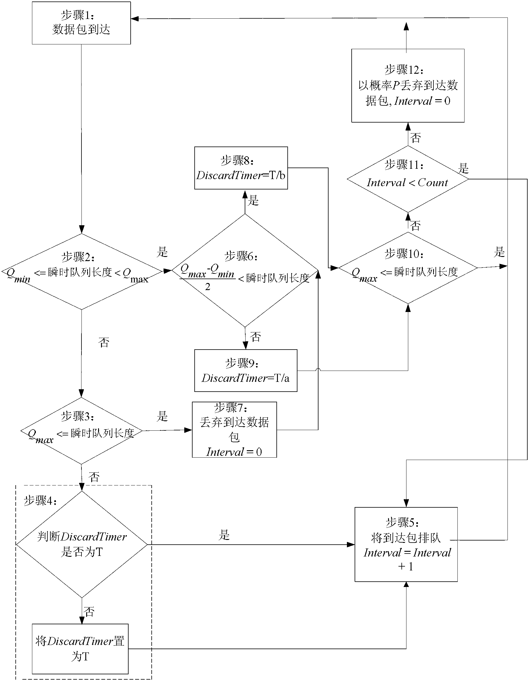
[0029] Specific implementation mode one: combine figure 1 Describe this embodiment, the packet loss method based on RED algorithm in the LTE described in this embodiment and LTE-A system, it comprises the following steps:

[0030] Step 1: when a data packet arrives at a UM RLC entity, calculate the number of data packets arriving at the buffer queue of the transport entity, where the number of data packets is the instantaneous queue length of the buffer queue;

[0031] Step 2: If the instantaneous queue length described in step 1 is less than the larger threshold Qmax and greater than or equal to the smaller threshold Qmin, go to step 6; otherwise go to step 3;

[0032] Step 3: If the instantaneous queue length is greater than or equal to the larger threshold Qmax, then go to step 7, otherwise go to step 4;

[0033] Step 4: Determine whether the set value of the timer DiscardTimer is T, if it is T, then go to step 5; if not, set it to T, and go to step 5;

[0034] Step 5: pu...

specific Embodiment approach 2

[0050] Embodiment 2: This embodiment is a further description of the packet loss method based on the RED algorithm in the LTE and LTE-A systems described in Embodiment 1. According to the maximum average delay that the system can bear, the maximum delay that the system can bear The packet loss rate and the set throughput of the system set the size of the smaller threshold Qmin.

specific Embodiment approach 3

[0051] Specific embodiment three: This embodiment is a further description of the packet loss method based on the RED algorithm in the LTE and LTE-A systems described in specific embodiment one. The parameter Count is a real number greater than or equal to zero. According to the LTE system and LTE-A System A determines the parameter Count according to the requirements of different data streams on packet loss rate and continuous packet loss rate.

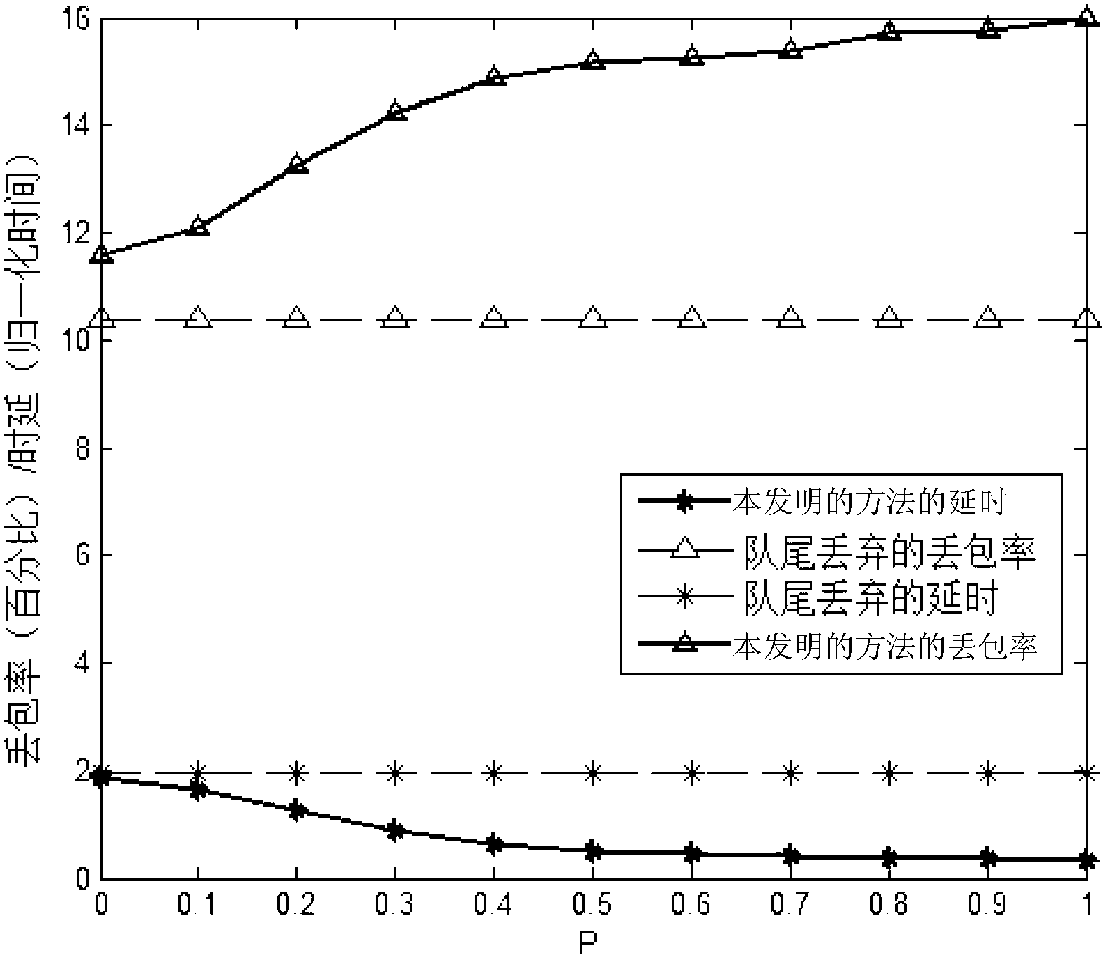
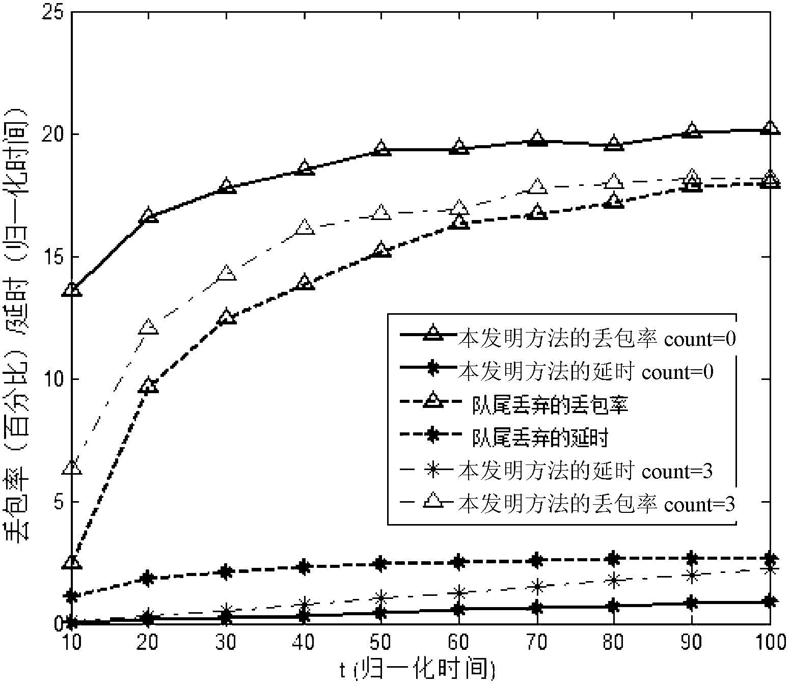
[0052] The Count value is set to a real number greater than or equal to zero. The smaller the Count value is set, the less effective it is for avoiding continuous packet loss; when the Count value is set to zero, its utility is zero. However, for the LTE system and the LTE-A system, the maximum utility of Count is fixed. The larger the Count value is, the greater the packet loss rate of the LTE system and LTE-A system is. The value of Count is determined according to the actual needs of the system. We demonstrate the benefits of the ...


PUM


Abstract

The invention discloses a packet loss method in a long term evolution (LTE) system and a long term evolution-advanced (LTE-A) system based on an RED (Random Early Detection) algorithm, relates to a packet loss method, and aims to solve the delay problem of long waiting of delay sensitive data flow in a radio link control (RLC) layer buffer of the LTE system and the LTE-A system caused by congestion and even buffer overflow. The packet loss is controlled and implemented by changing the set value of a discard timer in the LTE system and the LTE-A system and comparing an instantaneous queue length in the buffer with a minimal threshold Qmin and a maximal threshold Qmax. The randomness of a probability P ensures the randomness and fairness of the packet loss, and is favorable for the algorithm to avoid continuous packet loss. The method provided by the invention is used for implementing the packet loss in the LTE system and the LTE-A system.

Description

technical field [0001] The invention relates to a packet loss method, in particular to a packet loss method based on RED algorithm in LTE and LTE-A systems. Background technique [0002] Third Generation Partnership Project (3 rd Generation Partnership Project, 3GPP) standards organization launched the third generation (the3 rd Generation, 3G) long-term evolution (Long Term Evolution, LTE) and system architecture evolution (System Architecture Evolution, SAE) two major research and standardization work plans. As one of the sublayers of LTE, the radio link control (Radio Link Control, RLC) sublayer is responsible for segmenting or concatenating the arriving RLC service data unit (Service Data Unit, SDU). The RLC entity provides a transparent mode (Transparent Mode, TM), an unacknowledged mode (Unacknowledged Mode, UM) and an acknowledged mode (Acknowledged Mode, AM). In these three modes, UM RLC is responsible for carrying delay-sensitive data streams. [0003] In actual ...

Claims


Application Information

Patent Timeline
Patent Type & Authority Applications(China)
IPC IPC(8): H04L1/00
Inventor 于启月郑艺
Owner HARBIN INST OF TECH
Learn More