Method and system for detecting physical topological link

A physical topology and physical technology, applied in the direction of wireless communication, electrical components, etc., can solve problems such as errors, reduce the probability of physical topology connection errors, and fail to know the wrongly connected devices in time, so as to improve work efficiency and labor costs. Effect

Active Publication Date: 2012-11-28
苏州医疗器械产业发展集团有限公司
View PDF5 Cites 8 Cited by
  • Summary
  • Abstract
  • Description
  • Claims
  • Application Information

AI Technical Summary

Problems solved by technology

[0006] At present, there are only some solutions to reduce the probability of physical topology connection errors, and there is no solution to detect physical topology connection errors after a physical topology connection error occurs. Therefore, when an error occurs in the connected RRU, the device that is connected to the wrong device cannot be notified in time.

Method used


Image

  • Method and system for detecting physical topological link
  • Method and system for detecting physical topological link
  • Method and system for detecting physical topological link

Examples


Embodiment 1

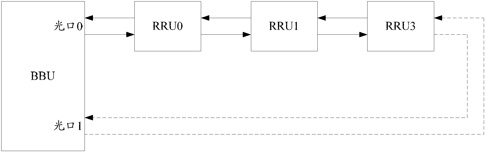
[0069] Figure 5 It is a schematic diagram of a network in Embodiment 1 of the method for detecting physical topology connections in the present invention. The network type configured in the background in this embodiment is a star network, such as Figure 5 As shown, in this embodiment, the RRUs under the optical port of the BBU are connected to form a ring network, and both the master optical port and the slave optical port of the BBU can analyze the physical optical port from the received optical port networking type information sequence information, but it is not the physical optical port information of the optical port itself. Therefore, it can be detected that the RRU connected to the optical port of the BBU is connected in a ring, forming a ring network, which is inconsistent with the network type configured in the background.

Embodiment 2

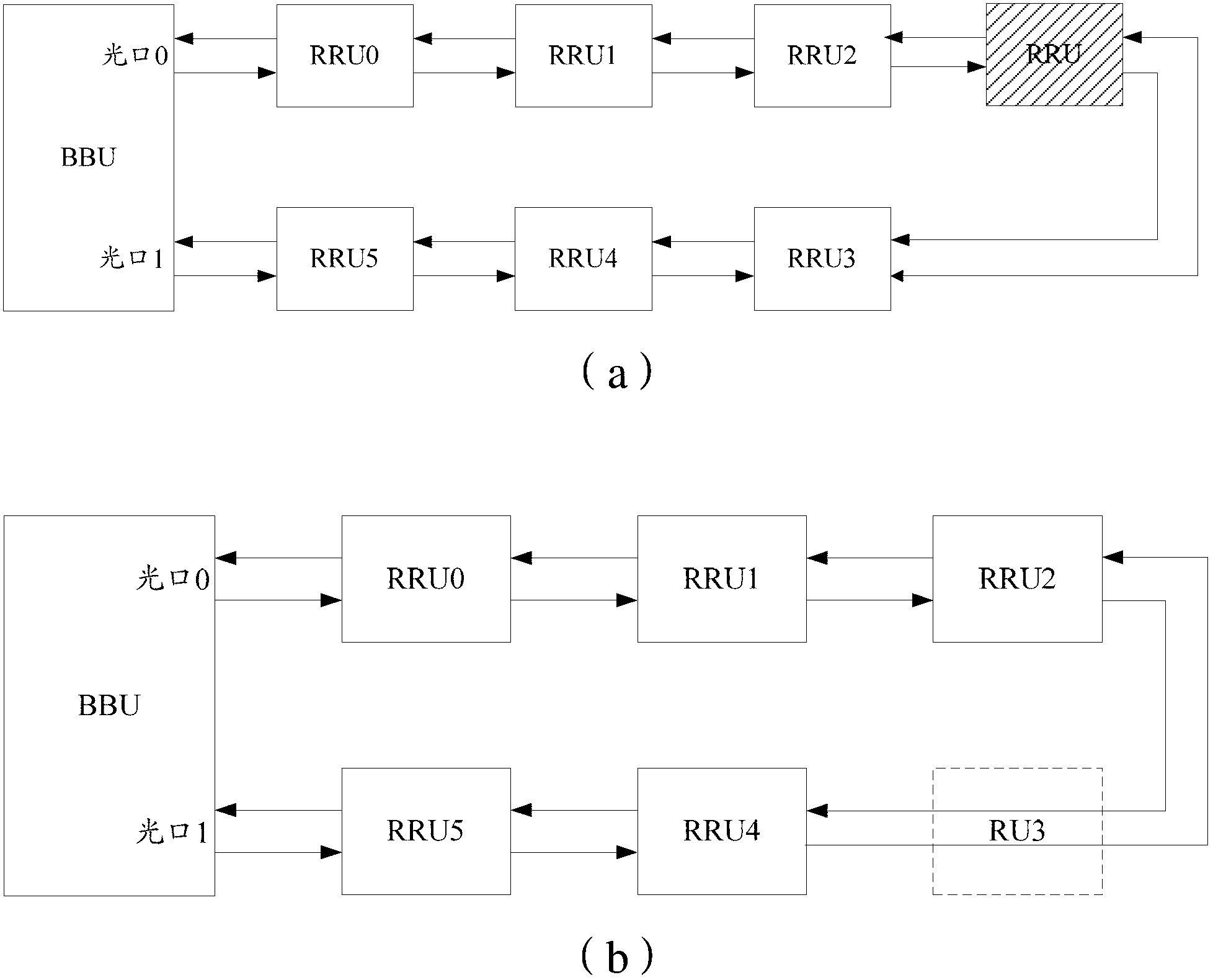
[0071] Image 6 It is a schematic diagram of the second embodiment of the method for detecting physical topology connections in the present invention. In this embodiment, the type of networking configured in the background is a ring network, and the BBU is connected to 6 RRUs, as shown in Image 6 As shown, the value of RRU-Index sent from the main optical port of the BBU to RRU0 is 0, and the value of RRU-Index sent from the optical port to RRU5 is 5. In the process of transferring from the optical port to the slave optical port, the value of RRU-Index increases. Therefore, at the last level RRU5 connected to the master optical port, the RRU-Index received by the slave optical port from RRU5 is 6. Similarly, the slave optical port transmits to the master During the process of the optical port, the value of RRU-Index is decremented, and the RRU-Index received by the master optical port from RRU0 is -1. Therefore, for the master optical port and the slave optical port, the issu...

Embodiment 3

[0073] Figure 7 It is a schematic diagram of the third embodiment of the method for detecting physical topology connections in the present invention. In this embodiment, the type of networking configured in the background is a ring network, and the BBU is connected to 6 RRUs, as shown in Figure 7 As shown, the value of RRU-Index sent from the main optical port of the BBU to RRU0 is 0, and the value of RRU-Index sent from the optical port to RRU5 is 5. During the transfer process from the optical port to the slave optical port, the value of RRU-Index increases. Therefore, at the last level of RRU5 connected to the master optical port, the RRU-Index received from RRU5 by the slave optical port is 4. Similarly, the slave optical port transmits to the master During the process of the optical port, the value of RRU-Index is decremented, and the RRU-Index received by the master optical port from RRU0 is 1. Therefore, for the master optical port and the slave optical port, the RRU-...


PUM


Abstract

The invention discloses a method for detecting a physical topological link. The method comprises the following steps of: detecting a current networking type; and if the detected networking type is different from a pre-configured networking type, carrying out alarming on a networking type error. The invention further provides a system for detecting the physical topological link. According to the technical scheme provided by the invention, an abnormal condition that an RRU (Remote Radio-Frequency Unit) which is actually connected under a BBU (Base Band Unit) is different from an RRU which is pre-configured by a background can be detected.

Description

technical field [0001] The invention relates to the field of mobile communication, in particular to a method and system for detecting physical topology connections. Background technique [0002] At present, there are two main networking modes in the remote radio mode in the mobile communication system, one is a star network, and the other is a ring network. With the advancement of technology, under the current baseband unit (BBU, Baseband Unit) + remote radio-frequency unit (RRU, Remote Radio-Frequency Unit) distributed base station, the number of RRUs connected to one BBU is increasing, and the radio remote mode The networking form of the network is becoming more and more complex, so it is necessary for the testers and field project implementation personnel to have a higher technical identification ability to connect the equipment correctly, and it also increases the cost of testing and project implementation. [0003] In view of the current increasingly complex networking...

Claims


Application Information

Patent Timeline
Patent Type & Authority Applications(China)
IPC IPC(8): H04W24/04
Inventor 蒋智军杨孝民余金清万娟杜超
Owner 苏州医疗器械产业发展集团有限公司
Why Eureka
Try Eureka