
Offset printing device

An offset printing and gantry technology, applied in printing, printing presses, rotary printing presses, etc., can solve the problems of inability to make the transfer cylinder, difficult to achieve the positional accuracy of the electrode pattern, etc., to achieve improved reproducibility, high reproducibility, high position The effect of precision

Inactive Publication Date: 2012-11-28
IHI CORP
View PDF8 Cites 2 Cited by
  • Summary
  • Abstract
  • Description
  • Claims
  • Application Information

AI Technical Summary

Problems solved by technology

Therefore, even if the position in the front-rear direction between the left and right movable frames 12 is very small, the transfer cylinder 13 cannot be made to face the unillustrated relief plate fixed on the fixed frame 9 and as a printing plate. Object's substrate
Therefore, even if the printing accuracy can meet the conventional requirements, it is difficult to achieve the very high positional accuracy in the case of suppressing the positional deviation of the fine printed pattern to a few μm, which is required for electrode pattern formation and the like.

Method used


Image

  • Offset printing device
  • Offset printing device
  • Offset printing device

Examples


Embodiment Construction

[0063] Embodiments of the present invention will be described below with reference to the drawings.

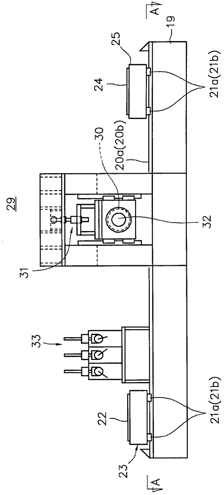
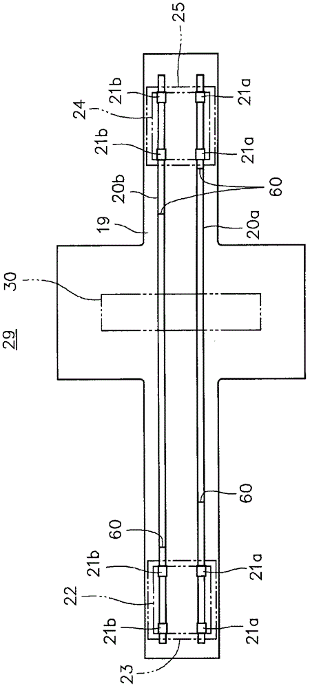
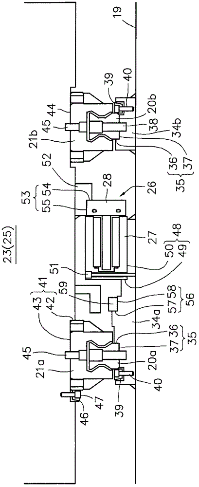
[0064] Figure 1 ~ Figure 3 An offset printing apparatus according to one embodiment of the present invention is shown.

[0065] First, the overall configuration of an offset printing apparatus according to an embodiment of the present invention will be described in outline. The offset printing device includes: a horizontal stand 19; a pair of left and right guide rails 20a, 20b arranged on the upper side of the horizontal stand 19 and extending in one direction (X-axis direction); The printing plate table 23 supporting the flat printing plate 22; the printing object table 25 which is arranged on the upper side of each guide rail 20a, 20b and can support a flat printing object 24 such as a substrate; and the left and right sides arranged on each guide rail 20a, 20b 2 each, 4 guide blocks 21a, 21b in total. The printing plate table 23 and the printing target table 25 are sli...


PUM


Abstract

An offset printing device is provided with a trestle, a guide rail provided on the trestle, a plurality of guide blocks provided on the guide rail, plate tables which move with a part of the plurality of guide blocks, print target tables which move with another part of the plurality of guide blocks, and a blanket roll provided above the trestle; wherein the blanket roll is sequentially brought into contact with plates held by the plate tables and print targets held by the print target table from above to perform transfer from the plates to the blanket roll and retransfer from the blanket roll to the print targets; a portion of the upper surface of the trestle where the guide rail is arranged is provided with a step portion for positioning configured by a vertical surface formed by machining to have higher linearity, and a horizontal surface; and a side surface and the bottom surface of the guide rail are abutted and secured on the vertical surface and the horizontal surface of the step portion, respectively.

Description

technical field [0001] The present invention relates to an offset printing apparatus for printing a fine printing pattern on a printing object with high printing accuracy, as in the case of forming an electrode pattern on a substrate by printing. [0002] This application claims priority based on Japanese Patent Application No. 2009-138698 for which it applied in Japan on June 9, 2009, and uses the content here. Background technique [0003] One of the printing techniques is offset printing. In offset printing using a gravure plate, the ink is temporarily transferred (received) from the inked gravure plate to a rotating blanket roll, and then the ink is retransferred from the blanket roll to the printing object (print). Thereby, the above-mentioned intaglio printing pattern can be printed on the surface of the printing object with good reproducibility. [0004] In recent years, as a method of forming an electrode pattern (conductive pattern) of a liquid crystal display or...

Claims


Application Information

Patent Timeline
Patent Type & Authority Applications(China)
IPC IPC(8): B41F3/20B41F3/36B41F17/14H05K3/12
CPCB41F3/56H05K3/12B41F3/60B41F3/51B41F3/26B41F3/20B41F3/36
Inventor 斎藤浩
Owner IHI CORP
Learn More