Torque tool

A tool and torque technology, applied in the field of angle/torque wrench, can solve the problems of rapid dirtying of the clamping unit, increased wear, wrong tripping torque, etc., to prevent pollution or even interference, and prevent foreign matter from intruding Effect

Inactive Publication Date: 2012-12-05
HAZET WERK HERMANN ZERVER
View PDF10 Cites 4 Cited by
  • Summary
  • Abstract
  • Description
  • Claims
  • Application Information

AI Technical Summary

Problems solved by technology

[0014] The actuation of the torque wrench is made difficult especially when adjusting the tripping torque due to the slender lever design due to the construction
Possible wear or breakage of the lever requires costly repair measures, since the clamping unit needs to be disassembled
In the case of defective levers, the use of torque wrenches is strongly restricted due to this
Due to the construction, the open construction, especially in daily practice, leads to rapid soiling of the clamping unit, which can lead to incorrect display of the set tripping torque and lead to increased wear

Method used


Image

  • Torque tool
  • Torque tool
  • Torque tool

Examples


Embodiment Construction

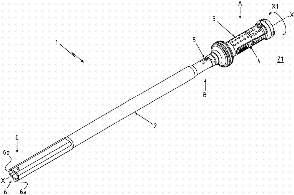
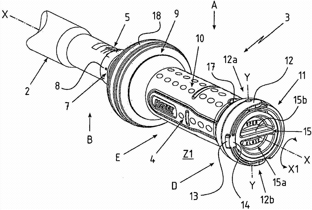
[0053] figure 1 A perspective view of the torque tool 1 according to the invention is shown. Here, now comes the adjustable torque wrench. The torque tool 1 has a tubular tool shaft 2 which extends in its longitudinal direction X. On the Toolbar—About figure 1 In view of the view—the right-hand end section A is provided with a handle 3 , which is rotatably mounted on the tool shaft 2 about the longitudinal axis X in the direction X1.

[0054] The handle 3 is directly or indirectly coupled to a clamping unit (not further shown) within the handle 3 and / or the tool shaft 2 . By turning the handle 3 , in a manner not shown further, the helical spring is clamped or unloaded, via which helical spring the tightening torque to be applied accordingly is preadjusted.

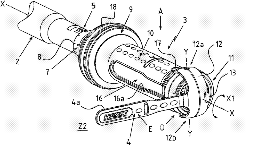
[0055] The handle 3 also has a folding lever 4 which bears against the handle 3 in its now-shown home position Z1 . A scale 5 is provided in the transition region B of the tool shaft 2 to the handle 3 , which can hav...


PUM


Abstract

The invention relates to a torque tool, particularly to an angle turning/torque wrench, and the torque tool has a tool rod (2) and a handle (3) arranged on an end part segment (A) of the tool rod. The handle (3) is rotatably supported around the longitudinal axis (X) of the tool rod (2), and an inner part(s) of the handle (3) or/and the tool rod (2) is/are provided with a clamping unit(s). Through the clamping unit(s), corresponding tripping torque can be adjusted by rotating the handle (3) relative to the tool rod (2). According to the invention, the handle (3) has a folding rod (4), and the folding rod (4) bears against the handle (3) in an initial position and can be transferred to an adjusted position (Z2) which transversely extends relative to the longitudinal axis (X).

Description

technical field [0001] The invention relates to a torque tool, in particular an angle / torque wrench, according to the features stated in the preamble of claim 1 . Background technique [0002] Bolted connections are among the most frequently used connection types in machine building. In order to generate sufficient clamping force between the detachably connected components, the screws and nuts used for this purpose are tightened by means of suitable screw tools. The screw tool has a contour that can engage the threaded connection in order to transmit the required torque. In addition to the force required for this and expended manually by the user, this force can also be generated, for example, by means of an electric, pneumatic or hydraulic drive. [0003] In particular when transferring muscular working forces, screw tools are used which can be attached perpendicular to the longitudinal direction of the screw connection and which are used to generate particularly high tor...

Claims


Application Information

Patent Timeline
Patent Type & Authority Applications(China)
IPC IPC(8): B25B23/16B25B23/142
CPCB25B23/1427B25G1/005
Inventor T・拜尔特A・里塞P・韦尔普
Owner HAZET WERK HERMANN ZERVER
Why Eureka
Try Eureka