Twist beam axle provided with Watt linkage

A technology of watt connecting rod and torsion beam shaft, applied in the direction of interconnection system, elastic suspension, vehicle spring, etc., can solve the problems of high cost, increase the overall weight of the torsion beam shaft, complex structure of the watt connecting rod, etc., to reduce the complexity , the effect of high driving comfort

Active Publication Date: 2012-12-05
FORD GLOBAL TECH LLC
View PDF7 Cites 7 Cited by
  • Summary
  • Abstract
  • Description
  • Claims
  • Application Information

AI Technical Summary

Problems solved by technology

The disadvantage of this system is that it is relatively expensive, and the structure of the Watts linkage connected to the trailing arm via a radial arm is complex, which adds to the overall weight of the torsion beam shaft and other problems due to the higher number of components required
In addition, the pivot point of the connection between the radial arm and the Watts linkage is relatively closer to the interior of the vehicle, i.e. away from the center plane of the wheel towards the center of the vehicle, which has an adverse effect on the kinematic characteristics of the wheel suspension system

Method used


Image

  • Twist beam axle provided with Watt linkage
  • Twist beam axle provided with Watt linkage
  • Twist beam axle provided with Watt linkage

Examples


Embodiment Construction

[0046] In different drawings, the same parts are always given the same reference signs, so these parts are usually only described once.

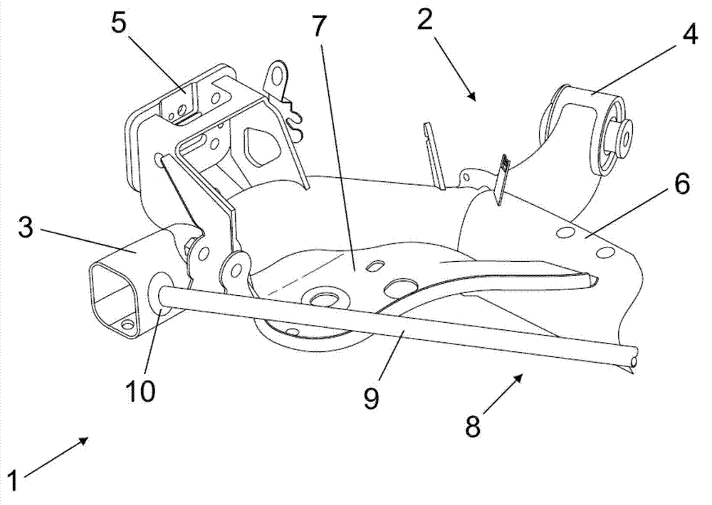
[0047] figure 1 A partial perspective view of an example of a first embodiment of a wheel suspension system 1 for non-steered wheels of a motor vehicle according to the invention is shown. The wheel suspension system 1 includes a torsion beam axle 2 . With respect to the direction of travel of the motor vehicle, figure 1 Only the left part of the torsion beam shaft 2 is shown. Since the torsion beam shaft 2 is designed to be substantially symmetrical with respect to the longitudinal center plane of the vehicle, the left side components of the wheel suspension system 1 described below are correspondingly provided on the right side of the wheel suspension system 1 . In the following description, it is not particularly specified that the specific components of the wheel suspension system 1 are only arranged on one side of the vehicle. This ...


PUM


Abstract

The invention provides to a twist beam axle provided with a Watt linkage, relating to a wheel suspension system for non-steered wheels (16) of a motor vehicle, which comprises a twist beam axle which comprises two wheel-supporting trailing arms (3, 13) pivotally mounted on a motor vehicle body (15) and a cross member (6) connecting the trailing arms (3, 13) together, and a Watt linkage (8) also connecting the trailing arms (3, 13) together, wherein at least one articulated holder (10) being integrated in each trailing arm (3, 13) itself for articulated coupling of the Watt linkage (8).

Description

technical field [0001] The invention relates to a wheel suspension system for non-steered wheels of a motor vehicle having a twist beam axle and a Watt linkage. Background technique [0002] Such wheel suspension systems with torsion beam axles are known per se, as is the wide application of Watt linkages in various technical fields involving wheel suspension systems. Typically, Watts linkages are provided on rigid shafts to firstly achieve more precise lateral guidance of the rigid shaft under lateral forces acting on the rigid shaft, and secondly, to allow the required compliant steering behavior of the rigid shaft, For example, towards the toe-in (toe-in) adjustment. [0003] For example, such a vehicle suspension system is known from the patent document DE2742426A1. In this wheel suspension system, the transverse member forms the rigid axle and connects the outer pivot points of the wheel together. One end of a trailing arm is disposed directly on the cross member. B...

Claims


Application Information

Patent Timeline
Patent Type & Authority Applications(China)
IPC IPC(8): B60G21/05
CPCB60G9/025B60G2200/342B60G2200/34B60G21/051B60G2200/21B60G2202/1362B60G2204/421
Inventor 保罗·赞德伯尔根安德列斯·卡利茨西奥·屈佩尔斯
Owner FORD GLOBAL TECH LLC
Why Eureka
Try Eureka