Long stroke magnetic suspension shock absorber

A magnetic levitation and long-stroke technology, applied in the direction of spring/shock absorber, magnetic spring, spring, etc., can solve the problems of small magnetic levitation force, noise transmission, short stroke, etc., achieve stable mechanism, increase stroke, and low manufacturing cost Effect

Inactive Publication Date: 2016-01-20
GUANGXI UNIV
View PDF6 Cites 3 Cited by
  • Summary
  • Abstract
  • Description
  • Claims
  • Application Information

AI Technical Summary

Problems solved by technology

[0006] The purpose of the present invention is to address the shortcomings and deficiencies of the above-mentioned shock absorbers, and to replace springs and hydraulic pistons with strong magnetic permanent magnet materials with opposite magnetic poles to make a new type of magnetic suspension shock absorber, so as to overcome the existing mechanical shock absorbers. The problems of friction, oil leakage and noise transmission, at the same time, the short stroke and small magnetic levitation force of the previous magnetic shock absorber are solved by adopting the structure of the conical magnet.

Method used


Image

  • Long stroke magnetic suspension shock absorber
  • Long stroke magnetic suspension shock absorber

Examples


Embodiment 1

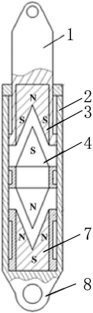
[0022] Such as figure 1 As shown, the long-stroke magnetic suspension shock absorber includes a shock absorber 2, an upper ring 1 and a lower ring 8, the upper ring 1 is connected with the shock absorber 2 by sliding, the lower ring 8 is fixedly connected with the shock absorber 2, and the top is permanently connected. The magnet 3 is connected with the upper suspension ring 1, the bottom permanent magnet 7 is connected with the lower suspension ring 8, and a conical floating permanent magnet A4 is connected with the shock absorber 2 in sliding fit, and is suspended between the top permanent magnet 3 and the bottom permanent magnet 7 in balance , the top permanent magnet 3 and the bottom permanent magnet 7 are provided with notches that can be adapted to the conical suspended permanent magnet A4.

[0023] During shock absorption, the upper ring 1, the top permanent magnet 3 and the conical suspension permanent magnet A4 reciprocate in the shock absorber 2 to achieve the purpos...

Embodiment 2

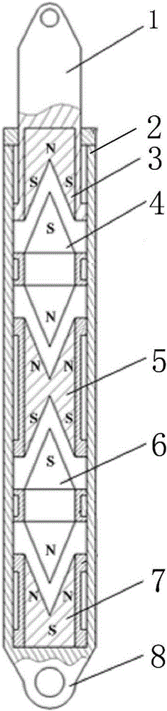
[0025] Such as figure 2 As shown, the long-stroke magnetic suspension shock absorber includes a shock absorber 2, an upper ring 1 and a lower ring 8, the upper ring 1 is connected with the shock absorber 2 by sliding, the lower ring 8 is fixedly connected with the shock absorber 2, and the top is permanently connected. The magnet 3 is connected with the upper suspension ring 1, and the bottom permanent magnet 7 is connected with the lower suspension ring 8. In the shock absorber 2, the conical suspension permanent magnet A4, the concave side suspension permanent magnet A5, and the conical suspension permanent magnet B6 are kept balanced and suspended in turn. Between the top permanent magnet 3 and the bottom permanent magnet 7, both the top permanent magnet 3 and the bottom permanent magnet 7 are provided with a notch that can fit with the conical suspended permanent magnet A4.

[0026] When shock absorbing, through the hanging ring 1, the top permanent magnet 3 and the conic...


PUM


Abstract

The invention discloses a long-stroke magnetic suspension shock absorber. The long-stroke magnetic suspension shock absorber comprises a shock absorbing cylinder (2), and an upper hanging ring (1) and a lower hanging ring (8), which are arranged at two ends of the shock absorbing cylinder, wherein end permanent magnets are respectively arranged inside the upper hanging ring (1) and the lower hanging ring (8); the upper hanging ring (1) is slidably connected with the shock absorbing cylinder (2); the lower hanging ring (8) is fixedly connected with the shock absorbing cylinder (2); suspension permanent magnets and the end permanent magnets repel, and / or the suspension permanent magnets at the two adjacent ends repel each other; and the suspension permanent magnets keep balanced and are suspended between a top permanent magnet (3) and a bottom permanent magnet (7). According to the long-stroke magnetic suspension shock absorber, by using the repelling force of the permanent magnets, a shock absorbing effect is achieved.

Description

technical field [0001] The invention relates to a shock absorber, in particular to a long-stroke magnetic suspension shock absorber. Background technique [0002] At present, in vehicles and other occasions that require shock absorption, a mechanical shock absorber with a spring and a hydraulic piston in parallel is generally used. The spring acts as a buffer, and the piston acts as a damper. The external vibration and impact cause the vibration to have a large attenuation on the shock absorber, so as to maintain the comfort and stability of the vehicle or equipment. After long-term use of this type of shock absorber, the spring in it will relax or be damaged by fatigue due to repeated elastic deformation, making the shock absorber invalid and unusable; the seal of the hydraulic piston will cause oil leakage due to wear and aging , so that the shock absorber loses the effect of the damper. Because it is a contact shock absorber, some high-frequency noise signals generated ...

Claims


Application Information

Patent Timeline
Patent Type & Authority Patents(China)
IPC IPC(8): F16F6/00
Inventor 林义忠
Owner GUANGXI UNIV
Why Eureka
Try Eureka