Method for calibrating camera shooting or photographing device

A camera device and calibration method technology, applied in the field of measurement, can solve the problems of low calibration efficiency, trailing, multiple movement of calibration positions, etc.

Active Publication Date: 2012-12-05
SHENZHEN TAISHAN SPORTS TECH CO LTD
View PDF4 Cites 37 Cited by
  • Summary
  • Abstract
  • Description
  • Claims
  • Application Information

AI Technical Summary

Problems solved by technology

[0006] The purpose of the present invention is to overcome the defects and deficiencies of the prior art, provide a calibration method for a binocular stereo vision sensor system, and solve the problem of tailing caused by

Method used


Image

  • Method for calibrating camera shooting or photographing device
  • Method for calibrating camera shooting or photographing device
  • Method for calibrating camera shooting or photographing device

Examples


Embodiment Construction

[0049] The present invention will be further described below in conjunction with drawings and embodiments.

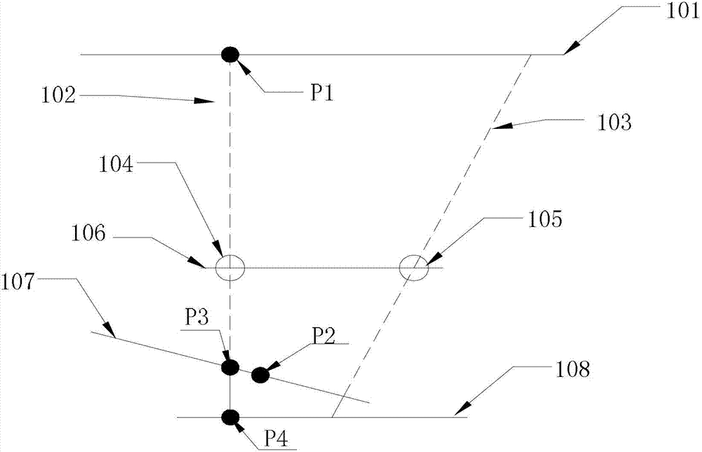
[0050] figure 1 A schematic diagram of parameter calibration of an imaging or camera device provided for a specific embodiment of the present invention. In this embodiment, the calibration of parameters of an imaging or photographing device having two imaging units is taken as an example for illustration. Such as figure 1 As shown, the calibration system composed of the camera or camera device includes a calibration target 101, a first camera unit 104 and a second camera unit 105, wherein the calibration target 101 is parallel to the first camera unit 104 and the second camera unit 105 Place and align the optical center of the lens of one of the camera units with the calibration target. In this embodiment, the optical center of the lens of the first camera unit 104 faces the calibration target. A motion recognizer 106 is installed on the camera unit, which is used to...


PUM


Abstract

The invention discloses a method for calibrating a camera shooting or photographing device, and belongs to the technical field of measurements. The method comprises the following steps of: presetting a position relationship between a calibration target and the camera shooting or photographing device; performing iterative computations according to coordinates of a preselected calibration point on the calibration target and a matching point of the calibration point on an actual image plane of the camera shooting or photographing device by utilizing an ideal lens imaging model, a lens distortion model and a collimation model; and calibrating the parameters of the camera shooting or photographing device. By the method, the position relationship between the calibration target and the camera shooting or photographing device is preset, the displacement calculation process of the optical center of the lens of the camera shooting or photographing device relative to the origin of coordinates of the plane of the calibration target is simplified, so that the whole calibration process is high-efficiency; and moreover, by the method, the problem that the parameters of the device are calibrated when the focusing is inaccurate can be effectively solved, the target pattern is only required to be photographed at one time, and the calibration efficiency is improved. In addition, the three-dimensional distance under the out-of-focus condition can be effectively measured.

Description

technical field [0001] The invention belongs to the technical field of measurement, and in particular relates to a calibration method of an imaging or photographing device, which can be applied to geometric calibration of images captured by cameras or cameras, camera calibration in computer stereo vision, and the like. Background technique [0002] The camera or camera lens is a non-ideal optical system, which is affected by the distortion parameters of the lens itself. When the image is captured by the camera or video camera, it not only affects the visual effect of the image, but sometimes affects the camera calibration accuracy in computer stereo vision. [0003] For a binocular stereo vision sensor system, the optical axes of the two camera lenses are usually non-parallel after the system is assembled (such as figure 1 shown as optical axis 102 and optical axis 103), the non-parallel optical axes will cause the imaging plane to shift (eg figure 1 The deviation of the ac...

Claims


Application Information

Patent Timeline
IPC IPC(8): G06T7/00
Inventor 陈济棠李乐师丹玮袁江龙
Owner SHENZHEN TAISHAN SPORTS TECH CO LTD
Why Eureka
Try Eureka