HVAC Control System And Method

A technology of buildings and models, applied in general control systems, control/regulation systems, heating and ventilation control systems, etc.

Inactive Publication Date: 2012-12-05
COMMONWEALTH SCI & IND RES ORG
View PDF4 Cites 50 Cited by
  • Summary
  • Abstract
  • Description
  • Claims
  • Application Information

AI Technical Summary

Problems solved by technology

Typically, this set point temperature is a fixed value, although prior a

Method used


Image

  • HVAC Control System And Method
  • HVAC Control System And Method
  • HVAC Control System And Method

Examples


Embodiment Construction

[0044] The preferred embodiments of the present invention will now be described by way of example only with reference to the drawings.

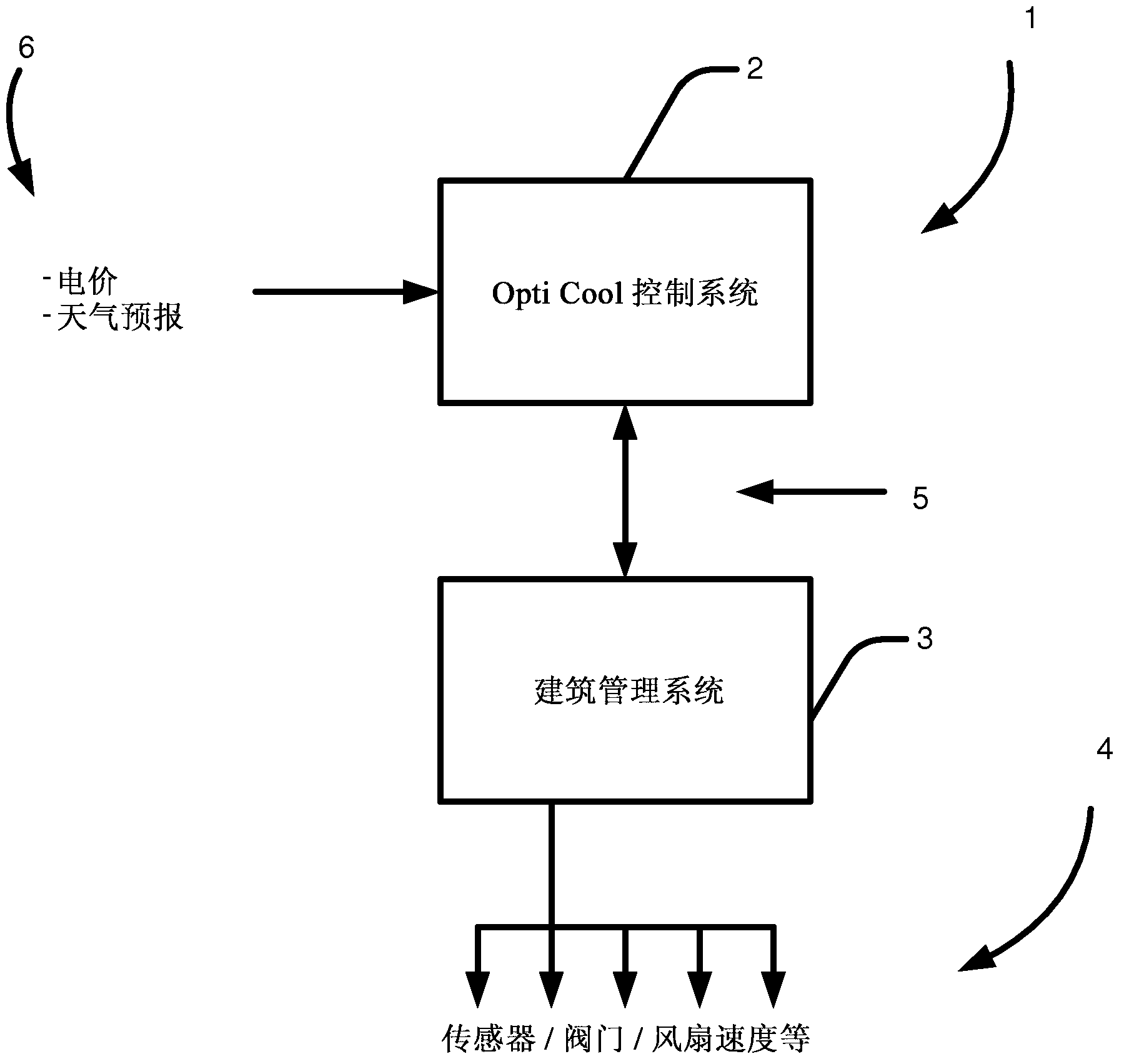
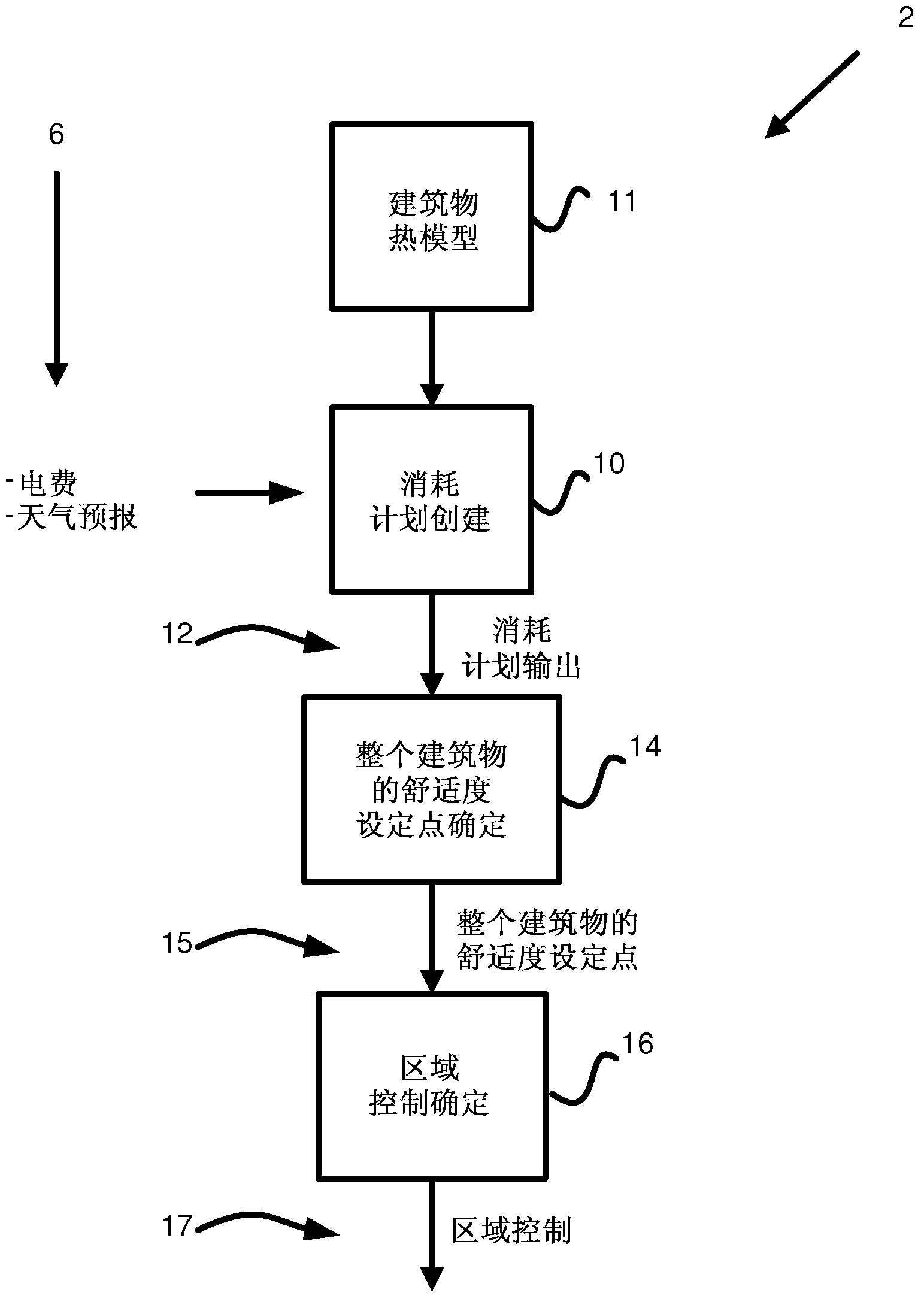
[0045] In a preferred embodiment, a control system is provided, wherein the basic set point of the system is not temperature, but human comfort ("predicted average thermal sensation index" measurement). In a preferred embodiment, a human body comfort target is first established, the temperature of the area is controlled according to the target, and then device parameters, such as valve and damper positions, fan speed, etc., are controlled to reach the comfort set point. This is in contrast to the prior art that generally uses a temperature-based set point scheme. For example, there may be multiple different temperature ranges that can achieve the same comfort set point. In terms of performance, by using human comfort as the basic control parameter, significant savings in energy and cost can be achieved while maintaining a certain level of human...


PUM


Abstract

A method of controlling the heating, ventilation and air conditioning (HVAC) system of a building, the method comprising the steps of: (a) developing an initial thermal model of the building, and continuously updating the thermal model over time; (b) utilising the thermal model to continuously develop a daily HVAC operating plan for the building; and (c) continuously examining a current HVAC operating plan and optimising the alignment of the current HVAC operation with the current HVAC operating plan.

Description

Technical field [0001] The present invention relates to effective systems and methods for heating, ventilation and air conditioning (HVAC) of buildings. In particular, the present invention provides a more effective climate control system for use in buildings. Background technique [0002] The widespread use of heating, ventilation and air conditioning (HVAC) systems has added great flexibility to building design and form. Even in harsh weather conditions, it can provide indoor comfort and is used to make buildings with poor thermal performance suitable for living. However, this flexibility requires costs. For example, in Australia, HVAC generally accounts for more than 60% of the energy use in commercial buildings [Australian Greenhouse Office, 1999], and it is an important contributor to greenhouse gas emissions and promotes The demand of the electricity network. [0003] Considerable research has been conducted on the optimal HVAC control strategy. These strategies consider ...

Claims


Application Information

Patent Timeline
IPC IPC(8): F24F11/053F24F11/02G05B13/04F24F11/76
CPCG05B15/02F24F2011/0057F24F2011/0091G05B2219/2642G05D23/1917F24F11/30F24F2120/20F24F11/62F24F11/46F24F11/52F24F2120/00F24F11/47F24F11/63F24F11/64G05B17/02F24F2140/60G05B2219/2614
Inventor 约翰·沃德乔舒亚·瓦尔格伦·普拉特
Owner COMMONWEALTH SCI & IND RES ORG
Why Eureka
Try Eureka