
Method of clearing an HVAC control fault code memory

Inactive Publication Date: 2006-08-10
YORK INT
View PDF10 Cites 12 Cited by
  • Summary
  • Abstract
  • Description
  • Claims
  • Application Information

AI Technical Summary

Benefits of technology

[0012] An advantage of the present invention is that it avoids the use of a manual onboard switch to clear the fault code memory and decreases or eliminates human intervention in the fault code clearing process.
[0013] Another advantage of the present invention is that it may increase production process speed by incorporating logic into the HVAC control that reduces the time required to clear the fault code memory versus the time required if using the onboard switch.
[0014] Still another advantage of the present invention is that it allows the fault code memory to be cleared after unit testing without requiring additional communications equipment and it avoids the need to make an additional connection for each unit built and tested.

Problems solved by technology

It is common for these types of controls to have some type of limited diagnostic capabilities, which typically result as an error code being translated as a blink code on an LED (light emitting diode), or as a display on a seven segment display.
In any event, a loss of power to the control board resulted in a reset of the controls and the loss of any error information without the possibility of recall.
So, when a repair technician went to evaluate a problem, because the home or business owner had usually already shut power down to the unit, the error code was no longer displayed.
If this is done before looking through a site-glass for any applicable error codes (if a site-glass is even provided on the access door), again the potentially valuable information of the error code would be lost.
Unless the error duplicates itself immediately upon test by the service technician, a lengthy trial and error period may be required to finally find and then fix the problem.
Pressing and releasing a control switch over and over may pose ergonomic problems for the worker and creates the possibility of damage to the control by mishandling.
Furthermore, the human element creates the possibility of other errors, such as those that may arise from inconsistent manipulation of the control switch and the like.
This equipment is expensive and generally atypical in HVAC unit testing environments.
Furthermore, making the communications connection to the control requires additional time, which slows production.

Method used


Image

  • Method of clearing an HVAC control fault code memory
  • Method of clearing an HVAC control fault code memory
  • Method of clearing an HVAC control fault code memory

Examples


Embodiment Construction

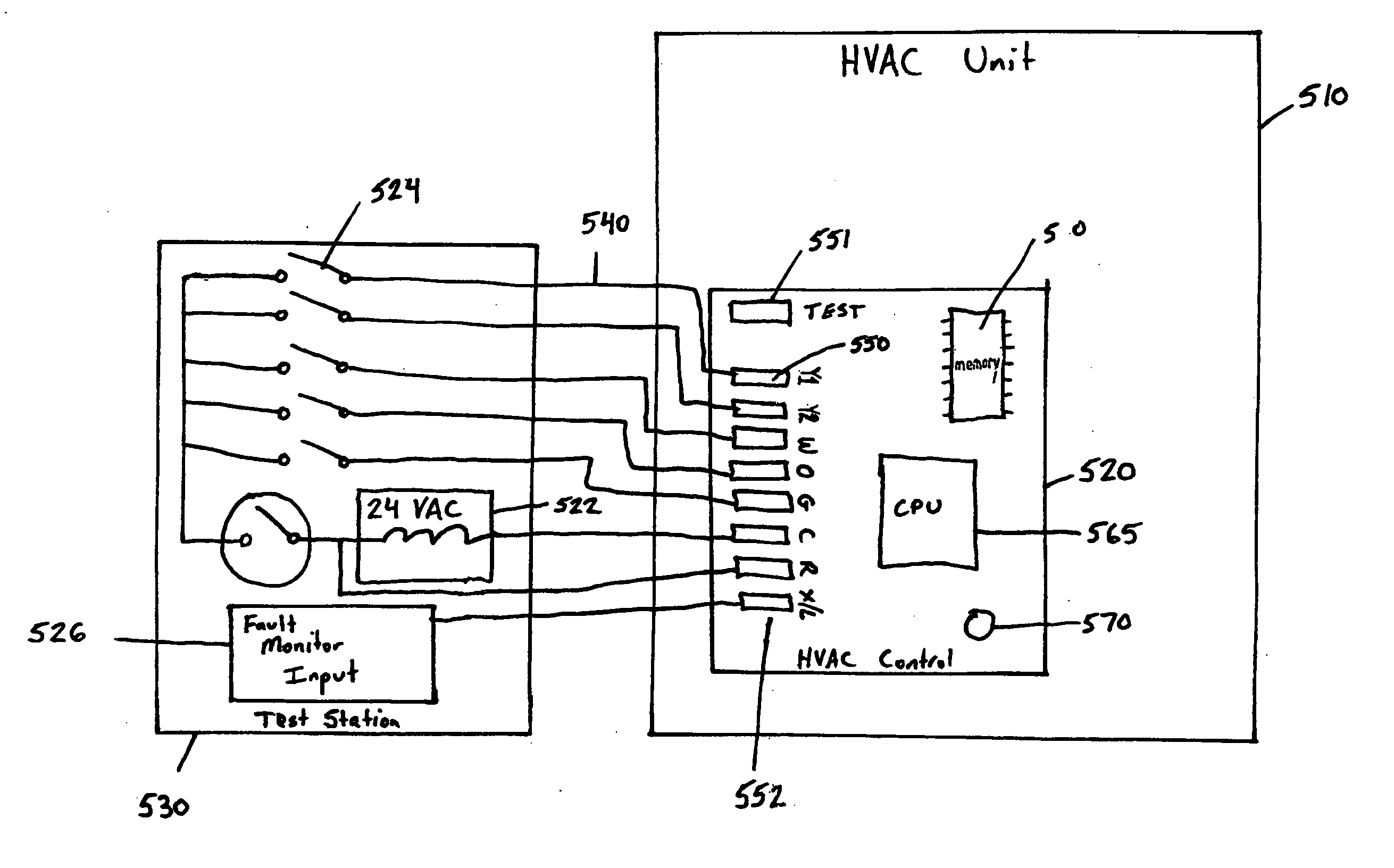
[0021] HVAC units, like most products, are typically tested after manufacture and prior to installation. In most test situations, a control board or panel of a control system of the HVAC unit is typically connected to a test station. The test station typically includes a power source and a number of switches. The test station sends control signals that replicate the control signals that would be received by the HVAC control or control system when the HVAC unit is installed as part of an operating HVAC system. For example, a furnace has a control that, when installed, is connected to a thermostat. The thermostat sends control signals during operation to instruct the furnace, for example, to turn on or off or to operate a fan. Likewise, the test station is wired to the HVAC control board to provide the same control signals during testing operations. By “control signals” is meant any analog signal or combination of analog signals sent to the HVAC control system to provide instructions ...


PUM


Abstract

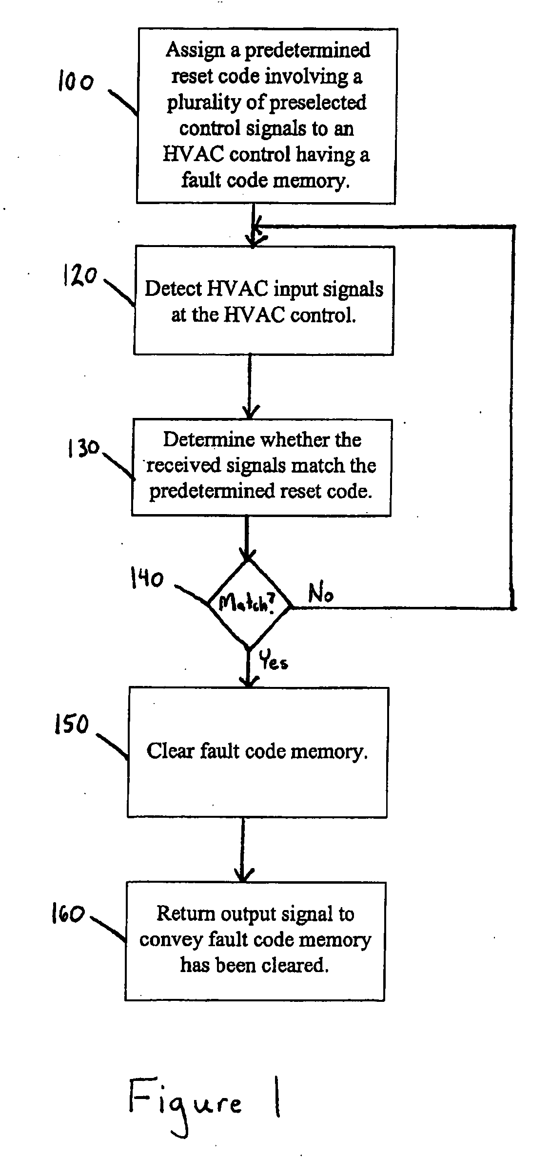
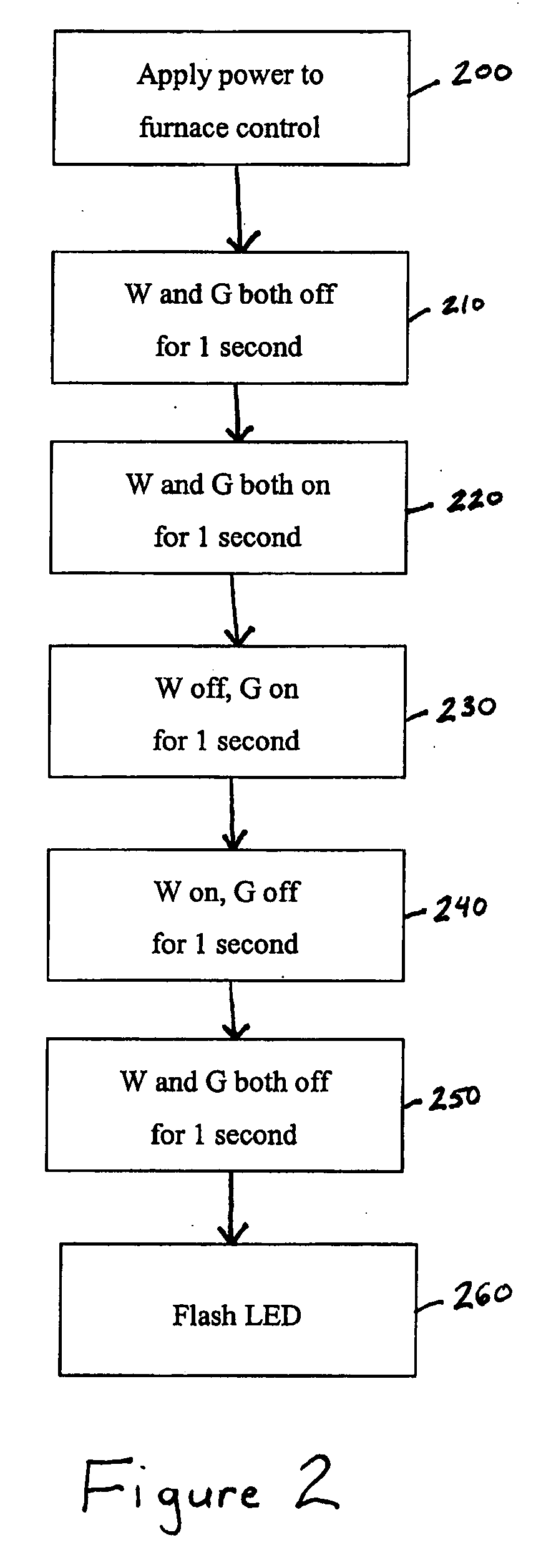
A method of clearing an HVAC control fault code memory is disclosed. The method includes assigning a predetermined reset code to an HVAC control system, the predetermined reset code comprising a plurality of control signals receivable by the HVAC control system, detecting control signals at the HVAC control system, determining whether the detected HVAC control input signals match the predetermined reset code and clearing a fault code memory of the HVAC control system in response to control signals matching the predetermined reset code.

Description

FIELD OF THE INVENTION [0001] The present invention is directed to a method of clearing an HVAC control fault code memory and more particularly to an automated method of clearing an HVAC control fault code memory using a predetermined set of control signals. BACKGROUND OF THE INVENTION [0002] Integrated or combined controls or control systems are common in the heating, ventilating and air conditioning (HVAC) industry. It is common for these types of controls to have some type of limited diagnostic capabilities, which typically result as an error code being translated as a blink code on an LED (light emitting diode), or as a display on a seven segment display. Until recently, most of these error codes were only shown while the actual error was happening, or while a lock-out condition persisted, while some controls might continue to display the fault code for a period of time after the fault condition abated. In any event, a loss of power to the control board resulted in a reset of th...

Claims


Application Information

Patent Timeline
IPC IPC(8): G06F11/00
CPCF24F11/0086F24F2011/0061G05B15/02G05B23/0291G05B2219/2642F24F11/30F24F11/63F24F11/52
Inventor HARROD, GREGORY RALPH
Owner YORK INT
Learn More