Image pickup device

A technology of a camera device and a camera element, which is applied in the fields of still cameras, image communication, television, etc., can solve the problems of lack of display responsiveness, and achieve the effect of improving display responsiveness.

Active Publication Date: 2015-07-22
PANASONIC SEMICON SOLUTIONS CO LTD
View PDF6 Cites 0 Cited by
  • Summary
  • Abstract
  • Description
  • Claims
  • Application Information

AI Technical Summary

Problems solved by technology

However, in the image pickup device described in Patent Document 2, the fixed-length coded data is read from the memory in the same manner as in Patent Document 1, and then displayed after being decompressed. , there is a problem of lack of display responsiveness

Method used


Image

  • Image pickup device
  • Image pickup device
  • Image pickup device

Examples


Embodiment 1

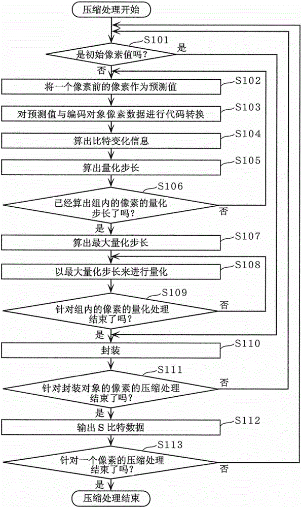
[0075] The imaging device according to Embodiment 1 of the present invention decompresses only a part of the compressed data, and displays the decompressed data. Accordingly, the imaging device according to one embodiment of the present invention can improve display responsiveness.

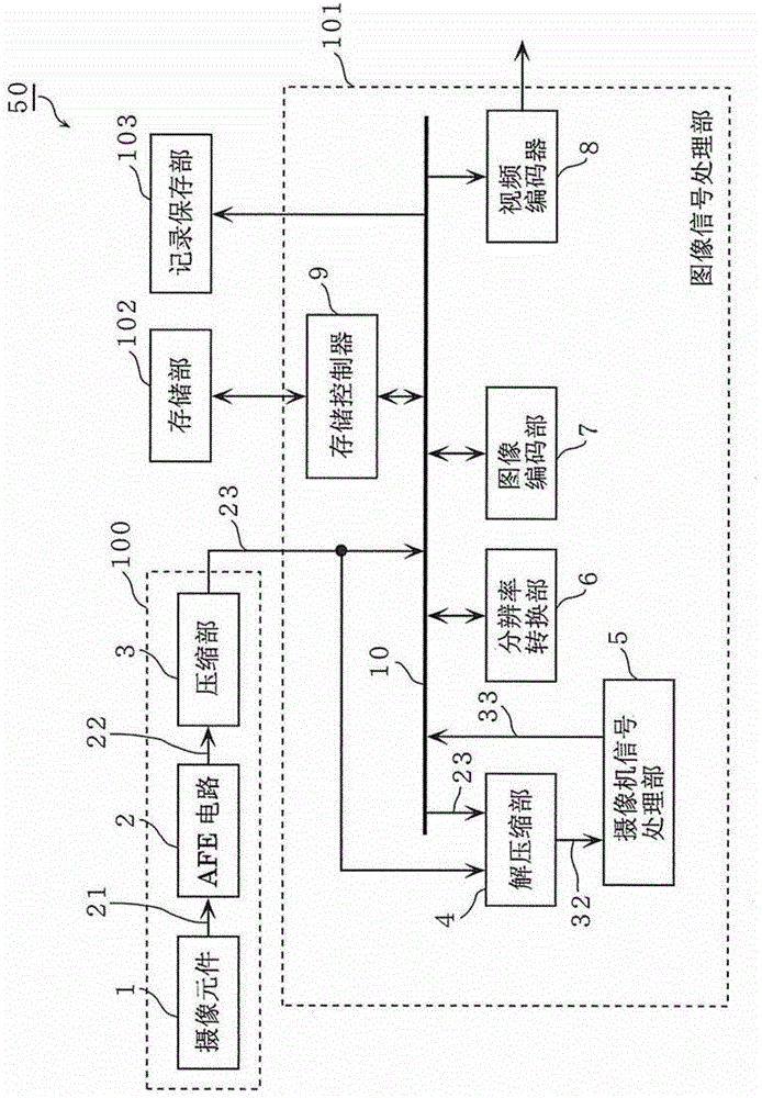
[0076] figure 1 It is a block diagram showing the configuration of the imaging device 50 according to the first embodiment of the present invention.

[0077] And, all or part of the imaging processing function of the imaging device in this embodiment is implemented by hardware such as LSI (Large Scale Integration: Large Scale Integrated Circuit), or a program executed by CPU (Central Processing Unit: Central Processing Unit) or the like. Realization, the following embodiments are also the same.

[0078] figure 1 The illustrated imaging device 50 includes an imaging unit 100 , an image signal processing unit 101 , a storage unit 102 , and a record storage unit 103 .

[0079] Furthermore, the im...

Embodiment 2

[0161] In the second embodiment, modifications of the decompression unit 4 and the camera signal processing unit 5 explained in the first embodiment will be described.

[0162] Figure 13 It is a block diagram showing the configuration of the camera signal processing unit 5A according to the second embodiment. Figure 13 The camera signal processing section 5A shown in addition to Figure 7 In addition to the configuration of the camera signal processing unit 5 shown, an exposure control unit 741 is further provided.

[0163] The exposure control unit 741 calculates the brightness level of the image data 22 using the partially decompressed data 32A, and controls the exposure amount (exposure amount) so that the image data 22 becomes a predetermined brightness level.

[0164] Figure 14 This is a sequence showing exposure control processing performed by the imaging device 50 according to the second embodiment.

[0165] First, in step S201 , the decompression unit 4 receives...

Embodiment 3

[0178] In the third embodiment, modifications of the decompression unit 4 and the camera signal processing unit 5 described in the first embodiment will be described.

[0179] And, in Embodiment 3, the compressed package data 23A contains Figure 9B Multiple specified pixel values ​​as shown.

[0180] Figure 17 It is a block diagram showing the configuration of the camera signal processing unit 5C according to the third embodiment. Figure 17 The shown camera signal processing section 5C is equipped with Figure 7 In addition to the configuration of the camera signal processing unit 5 shown, a focus control unit 743 is also provided.

[0181] The focus control unit 743 calculates the frequency characteristic of the pixel data 22A included in the partially decompressed data 32A, and performs focus control using the frequency characteristic.

[0182] Figure 18 It is a flowchart showing the procedure of focus control processing performed by the imaging device 50 according ...


PUM


Abstract

An imaging apparatus includes the following processing units. An imaging device generates first image data according to incident light. A compression unit performs fixed length coding on the first image data to generate first compressed data. A storage unit stores the first compressed data. A de-compression unit de-compresses only first designated data that is a part of the first compressed data so as to generate first partial de-compressed data. A signal processing unit corrects image quality of the first partial de-compressed data to generate first partial corrected image data. A display unit displays the first partial corrected image data.

Description

technical field [0001] The present invention relates to an imaging device, in particular to an imaging device for performing fixed-length encoding on image data. Background technique [0002] In recent years, as the number of pixels of imaging elements used in imaging devices such as digital still cameras and digital video cameras has increased, the amount of image data to be processed by integrated circuits mounted in the imaging devices has also increased. In order to process a large amount of image data, it is necessary to secure a bus width for data transfer in an integrated circuit, so it is considered to increase the operating frequency, increase the capacity of the memory, and the like. However, these are directly related to the increase in the cost of the imaging device. [0003] In general, in imaging devices such as digital still cameras and digital video cameras, data that has undergone all image processing in an integrated circuit is compressed before being reco...

Claims


Application Information

Patent Timeline
Patent Type & Authority Patents(China)
IPC IPC(8): H04N5/232H04N5/353H04N5/361H04N19/42
CPCH04N1/212H04N2101/00H04N5/353H04N1/0044H04N5/361H04N19/42H04N25/53H04N25/63
Inventor 高仓宪太郎中村研史
Owner PANASONIC SEMICON SOLUTIONS CO LTD
Why Eureka
Try Eureka