Check patentability & draft patents in minutes with Patsnap Eureka AI!

Circuit For Operating Light Emitting Diodes (LEDs)

A technology for driving circuits and control circuits, applied in the field of circuits for operating light-emitting diodes (LEDs), can solve problems such as reducing display quality or color rendering index

Active Publication Date: 2012-12-05
特里多尼克股份有限公司
View PDF4 Cites 4 Cited by
  • Summary
  • Abstract
  • Description
  • Claims
  • Application Information

AI Technical Summary

Problems solved by technology

[0007] However, there is usually also a spectral gap or at least one spectral valley 10 between the actual (e.g. blue) spectrum 8 of the lighting component chip and the second (yellow or red) converted spectrum 9 of the conversion layer, resulting in a reduced display quality or color rendering index

Method used


Image

  • Circuit For Operating Light Emitting Diodes (LEDs)
  • Circuit For Operating Light Emitting Diodes (LEDs)
  • Circuit For Operating Light Emitting Diodes (LEDs)

Examples


Embodiment Construction

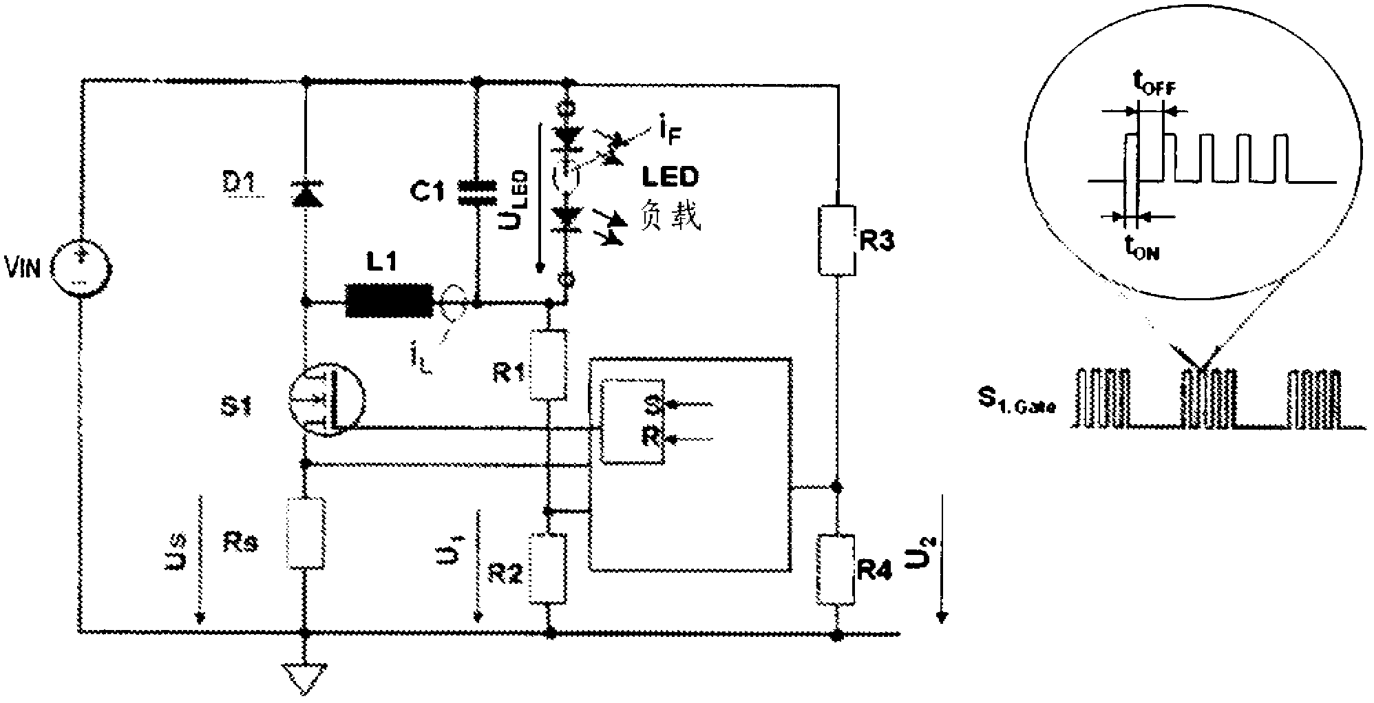
[0035] figure 1 A first exemplary embodiment of a circuit arrangement 130 according to the invention for controlling light-emitting diodes 34 is shown. Circuit arrangement 130 has a switching converter formed by choke coil L1 , capacitor C1 , freewheeling diode D1 , switch S1 and light-emitting diode 34 .

[0036] A control circuit, such as an IC (microcontroller, ASIC, combinations thereof, etc.) controls switch S1.

[0037] In this example, the switching converter is formed as a buck converter, however, other topologies such as a boost converter (see Figure 5 ), a flyback converter, PFC or even a buck-boost converter. A number of resistors ("shunts") are provided to monitor the current and voltage in the switching converter and across the light emitting diodes 34 . Therefore, resistor R S It is used to monitor the current flowing through the switch S1 while the switch S1 is on, where the shunt R S The voltage across the U S characterize the current.

[0038] current ...


PUM


Abstract

The invention proposes a driving circuit for provision of an operating current for at least one lighting means, such as e.g. a light emitting diode, the driving circuit comprising a switched converter (130) having a switch (SI) controlled by a control circuitry, wherein a choke (LI) is charged when the control circuitry control the switch in its conducting state and the choke is de- charged when the control circuits controls the switch in its non-conducting state, wherein by supplying an external signal or an internal feedback signal to the control circuitry, the control circuitry is designed to adapt the clocking of the switch in order to adapt the operating mode of the switched converter, to either of a continuous, borderline (transition, critical) and discontinuous conduction mode, CCM, BCM or DCM.

Description

technical field [0001] The invention relates to a circuit arrangement for operating light-emitting diodes and a method for achieving this object. Background technique [0002] Traditional light emitting diodes (LEDs) emit light in a limited spectral range. For example, figure 1 The spectra of blue 1 , green 2 , yellow 3 and red 4 LEDs are shown. Modules are known in which light-emitting diodes of different colors, for example blue and yellow (two LEDs), or red, green and blue (RGB), are combined such that the light of the individual light-emitting diodes is mixed, for example by means of a diffusing screen, and The mixed light appears white or the resulting spectrum 5 extends over the entire visible range. [0003] Although the light is substantially "white", there are valleys 6, 7 in the spectrum of the emitted light. These troughs have a detrimental effect because, for example, objects with colors within these gaps take on a very dull appearance. The color rendering q...

Claims


Application Information

Patent Timeline
IPC IPC(8): H05B33/08H05B44/00
CPCH05B33/0848H05B33/0815H05B33/0824H05B45/14H05B45/44H05B45/3725H05B45/375
Inventor 迈克尔·齐默尔曼爱德华多·佩雷拉
Owner 特里多尼克股份有限公司
Features
  • R&D
  • Intellectual Property
  • Life Sciences
  • Materials
  • Tech Scout
  • Unparalleled Data Quality
  • Higher Quality Content
  • 60% Fewer Hallucinations
Learn More