Drawing device

A molder and formwork technology, applied in the field of drafters, can solve problems such as hidden safety hazards, formwork slippage, inconvenient operation, etc., and achieve the effects of improving mold removal efficiency, rapid mold removal, and convenient operation.

Inactive Publication Date: 2012-12-12
SHENZHEN FUTAIHONG PRECISION IND CO LTD
View PDF7 Cites 7 Cited by
  • Summary
  • Abstract
  • Description
  • Claims
  • Application Information

AI Technical Summary

Problems solved by technology

However, since the C-shaped clip is generally large in size and heavy in weight, it is inconvenient to operate
And if the C-clamp is unbalanced, it will easily cause the template to slip, posing a safety hazard

Method used


Image

  • Drawing device
  • Drawing device
  • Drawing device

Examples


Embodiment Construction

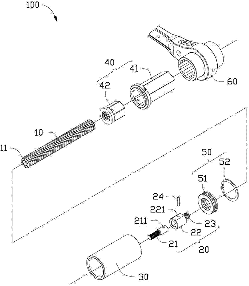
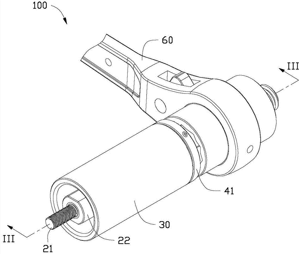
[0013] see figure 1 A preferred embodiment of the present invention provides a puller 100 , including a lead screw 10 , an adapter assembly 20 , a sleeve 30 , a nut assembly 40 and a transmission assembly 50 .

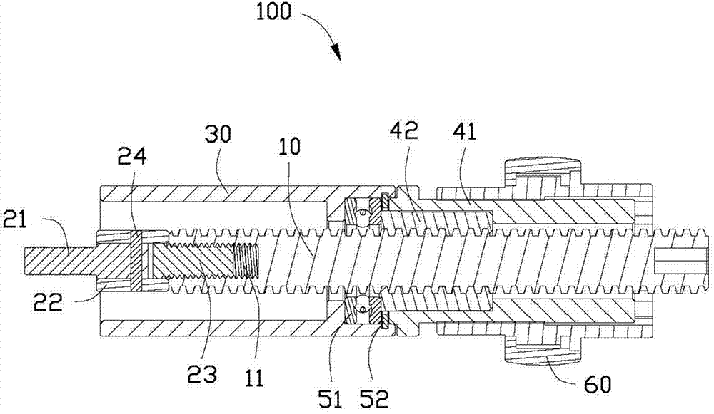
[0014] The lead screw 10 is approximately cylindrical, and its outer surface is provided with several threads, and the threads are 30-degree trapezoidal. One end of the lead screw 10 is provided with a screw hole 11 , and the screw hole 11 extends from one end of the lead screw 10 to the opposite end.

[0015] The adapter assembly 20 includes a screw 21 , a connecting portion 22 and a connecting rod 23 . The screw rod 21 is roughly cylindrical, and its outer surface is provided with several threads. The specific shape and structure of the screw rod 21 correspond to the shape and structure of the workpiece to be drawn, such as the shape and structure of the positioning screw and the positioning pin, and are used for fastening and connecting with the workpiece to be dr...


PUM


Abstract

The invention provides a drawing device used for drawing out to-be-drawn mould workpieces from a template. The drawing device comprises a screw rod, a rotating connection component and a nut component, the rotating connection component comprises a screw, a connecting portion and a connecting rod, one end of the screw is connected with a to-be-drawn mould workpiece by means of fastening, the other end of the screw is connected with the connecting portion, one end of the connecting rod is connected with the connecting portion to be connected with the screw through the connecting portion, the other end of the connecting rod is connected to the screw rod, and one end, away from the screw, of the screw rod is penetratingly arranged in the nut component. The nut component is operated to rotate to further drive the screw rod and the screw to move back and forth, so that the to-be-drawn mould workpiece moves along with the screw and the screw rod to be drawn out from the template.

Description

technical field [0001] The invention relates to a fitter tool, in particular to a mold puller. Background technique [0002] In the production work of the fitter, when disassembling the mold, it is often necessary to pull out the positioning screw and positioning pin fastened in the mold, that is, to carry out the drafting process. The existing method is to knock out the positioning screw and positioning pin from the template, or set up internal thread holes on the positioning screw and positioning pin, and then use another threaded rod to tighten the thread of the internal thread hole, and manually Pull the threaded rod to pull out the positioning screw and positioning pin. However, this manual operation method is laborious, slow in demoulding speed and low in efficiency. [0003] In addition, during the drafting process, it is necessary to use auxiliary tools such as C-clamps to lock the thimble plate and the male template, thereby shortening the distance between the tem...

Claims


Application Information

Patent Timeline
Patent Type & Authority Applications(China)
IPC IPC(8): B25B27/02
CPCB25B27/023Y10T29/53878
Inventor 胡建忠高杜喜
Owner SHENZHEN FUTAIHONG PRECISION IND CO LTD
Why Eureka
Try Eureka