Shaft lifting device for leaf springs suspension

A leaf spring and axle technology is applied in the field of axle lifting devices suspended by leaf springs. , the effect of long service life

Inactive Publication Date: 2012-12-12
东莞市永强汽车制造有限公司
View PDF6 Cites 2 Cited by
  • Summary
  • Abstract
  • Description
  • Claims
  • Application Information

AI Technical Summary

Problems solved by technology

[0002] Most of the axle lifting mechanisms of automobiles in the prior art adopt liftable air suspension. When the vehicle is heavily loaded, the liftable axle is put down. When the vehicle is lightly loaded, the liftable axle is lifted to distribute the axle load reasonably. Reduce fuel consumption and reduce tire wear, but the liftable air suspension is not only expensive, but also easy to damage, and the maintenance cost is high, which greatly increases the manufacturing and use costs of the vehicle
Although the cost of the vehicle with leaf spring suspension is low, it cannot realize the lifting of the axle, the reasonable distribution of axle load, the reduction of fuel consumption, and the requirements of reducing tire wear.

Method used


Image

  • Shaft lifting device for leaf springs suspension
  • Shaft lifting device for leaf springs suspension
  • Shaft lifting device for leaf springs suspension

Examples


Embodiment 1

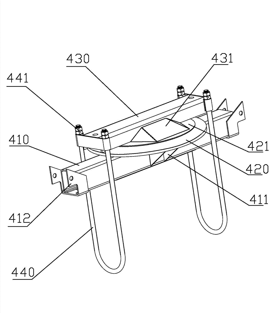
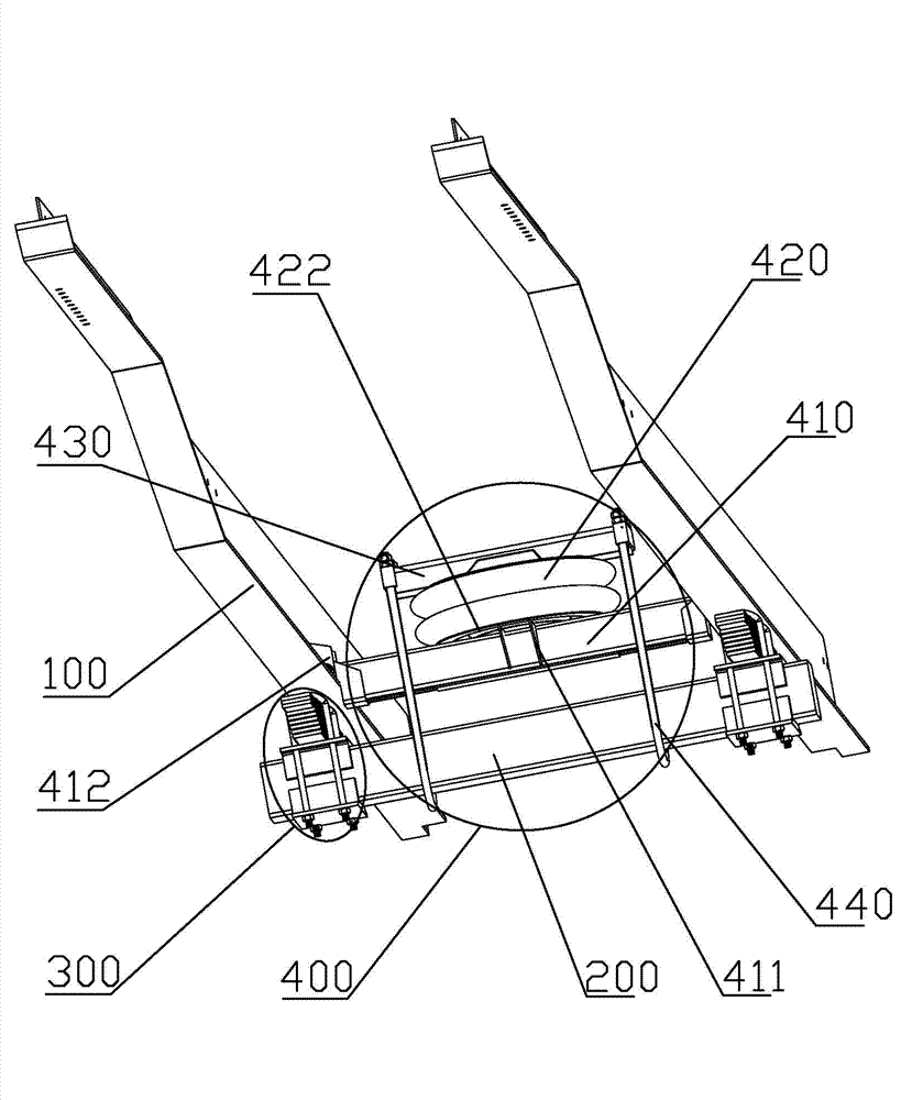
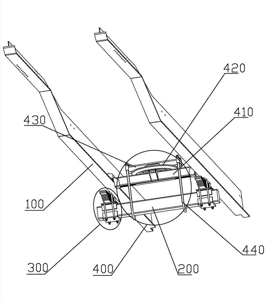
[0035] A kind of leaf spring suspension axle lifting device of the present invention, as Figure 1 to Figure 3 As shown, it includes a vehicle frame 100, an axle 200 and steel plate suspension mechanisms 300 respectively affixed to both ends of the axle 200. An axle lifting mechanism 400 is fixedly connected above the axle 200 and in the middle of the vehicle frame 100. The axle lifting mechanism 400 includes two The ends are respectively fixed to the fixed beam 410 of the vehicle frame 100, the airbag 420 which can be inflated and deflated and the movable beam 430 which are arranged on the fixed beam 410, the airbag 420 is arranged between the fixed beam 410 and the movable beam 430, and the movable beam Both ends of the 430 are fixedly connected to the lifting member 440, and the axle 200 is arranged on the lifting member 440.

[0036] The device relies on the inflation and deflation of the air bag 420 of the axle lifting mechanism 400 to lift and lower the axle 200. The dev...

Embodiment 2

[0046] The main technical solutions of this embodiment are the same as those of Embodiment 1, and the features not explained in this embodiment are explained in Embodiment 1, and will not be repeated here. The difference between this embodiment and embodiment 1 is:

[0047] like Figure 4 , Figure 5 As shown, longitudinal guide rails 450 are respectively provided above the two ends of the fixed beam 410 , and the two ends of the movable beam 430 are slidingly matched with the guide rails 450 respectively. When the airbag 420 is inflated or deflated, the movable beam 430 moves up and down with the airbag 420. At this time, the two ends of the movable beam 430 move up or down along the guide rail 450. The setting of this structure makes the integrity of the axle lifting mechanism 400 better. When the movable beam 430 moves up and down, it will not deviate from its position, causing the lifting member 440 to receive unnecessary torsion.


PUM


Abstract

The invention relates to the technical field of the shaft lifting mechanism of automobiles, in particular to a shaft lifting device for leaf springs suspension. The shaft lifting mechanism comprises a frame, a shaft and leaf suspension mechanisms fixedly connected with two ends of the shaft, respectively. The shaft lifting mechanisms are fixedly connected with the upper part of the shaft and the middle of the frame. The shaft lifting mechanism includes a fixed beam, the two ends of which are fixedly connected with the frame, respectively; an airbag which is arranged on the fixed beam and which is chargeable and dischargeable; and a movable beam. The airbag is arranged between the fixed beam and the movable beam, the two ends of the movable beam are connected with lifting components, respectively, and the shaft is arranged on the lifting components. The shaft is lifted up and down by the charge and discharge of the airbag of the shaft lifting mechanism, and the lift-up and lift-down of the shaft is achieved by the device. The loads are distributed rationally, the oil consumption is reduced, and the wear of tires is reduced. Furthermore, the device has the advantages of simple structure, firmness, high strength, long service life, and low manufacture cost.

Description

technical field [0001] The invention relates to the technical field of axle lifting mechanisms of automobiles, in particular to an axle lifting device suspended by leaf springs. Background technique [0002] Most of the axle lifting mechanisms of automobiles in the prior art adopt liftable air suspension. When the vehicle is heavily loaded, the liftable axle is put down. When the vehicle is lightly loaded, the liftable axle is lifted to distribute the axle load reasonably. Reduce fuel consumption and reduce tire wear, but the liftable air suspension is not only expensive, but also easy to damage, and the repair and maintenance costs are relatively high, which greatly increases the manufacturing and use costs of the vehicle. Although the vehicle with leaf spring suspension is relatively low in cost, it cannot achieve the lifting of the axle, and cannot achieve the requirements of rationally distributing the axle load, reducing fuel consumption, and reducing tire wear. Conte...

Claims


Application Information

Patent Timeline
IPC IPC(8): B60G17/052
Inventor 王特夫黄炜庆
Owner 东莞市永强汽车制造有限公司
Why Eureka
Try Eureka