Fuselage lateral and heading load combined application device and load application method

An application device and combined loading technology, applied in the direction of aircraft component testing, etc., can solve the problems of increased coordination and control difficulty, test protection, less loading points, etc., and achieve the effect of facilitating structural damage detection, reasonable distribution of loading points, and uniform load distribution.

Pending Publication Date: 2020-07-14
CHINA AIRPLANT STRENGTH RES INST
View PDF7 Cites 1 Cited by
  • Summary
  • Abstract
  • Description
  • Claims
  • Application Information

AI Technical Summary

Problems solved by technology

[0005] However, although the existing loading methods can meet the needs of full-scale aircraft structure fatigue test loads, the disadvantages are also obvious: first, setting multiple loading points will inevitably increase the loading nodes on the aircraft surface, resulting in the sticking of the aircraft surface. The large number of equipment affects the damage detection of the structural surface; second, the traditional heading load nodes are often unable to apply absolute heading loads due to the structural characteristics of the fuselage, but need to deviate from an angle to both sides, resulting in the addition of heading loads at the same time An unnecessary side load component; third, fewer loading points need to be used in each working condition, resulting in too concentrated load application, which is not conducive to the accurate distribution of structural load loading requirements; fourth, the increase of loading points makes With the increase of control system channels, the difficulty of coordinated control in the test is also greatly increased, which will easily lead to the system stepping and waiting or even test protection, which is not conducive to the efficient operation of fatigue tests

Method used


Image

  • Fuselage lateral and heading load combined application device and load application method
  • Fuselage lateral and heading load combined application device and load application method
  • Fuselage lateral and heading load combined application device and load application method

Examples


Embodiment Construction

[0037] In order to make the purpose, technical solutions and advantages of the implementation of this application clearer, the technical solutions in the embodiments of the application will be described in more detail below in conjunction with the drawings in the embodiments of the application.

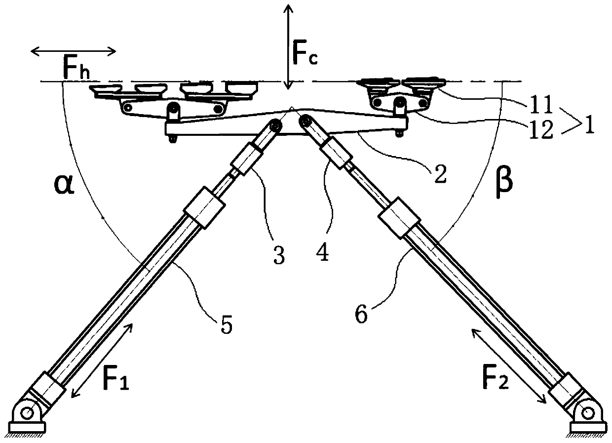
[0038] In order to apply the load for the ground strength test of the full-scale aircraft structure, it can not only meet the needs of various load applications in the test, but not increase the sticking nodes on the surface of the aircraft too much; it can accurately apply the lateral / heading load required in the test , Without causing the structure to bear unwanted side load components, this application provides a device and method for applying a combined lateral and heading load of the fuselage.

[0039] Such as figure 1 As shown, this application first provides an application device for the combined loading of fuselage lateral and heading loads. The application device mainly includes: ...


PUM


Abstract

The invention provides a fuselage lateral and heading load combined application device. The device comprises a loading lever device which is connected with a surface of a fuselage skin and used for applying a load to the fuselage skin, a combined loading lever, a first execution actuator and a second execution actuator, wherein two ends of the combined loading lever are each connected with at least one loading lever device and used for balancing loads applied to the loading lever devices, the first execution actuator and the second execution actuator are approximately symmetrically connected with the combined loading lever, and the first execution actuator and the second execution actuator are horizontally arranged in the same horizontal plane. Compared with a load applying device in the prior art, the fuselage lateral and heading load combined applying device provided by the invention can realize bidirectional loading, realizes application of heading and lateral loads through one setof lever system, reduces the adhesion amount of a structure surface load transfer medium, and is convenient for structure damage detection.

Description

Technical field [0001] This application belongs to the technical field of aircraft structural strength testing, and in particular relates to a device and a method for applying a combined lateral and heading load of the fuselage. Background technique [0002] In the ground strength test of a full-scale aircraft structure, distributed hydraulic actuators are usually used to apply loads to the aircraft structure through a multi-point coordinated loading control system to simulate the true force of the aircraft in use, and determine the structure by measuring the response of the structure Whether the strength meets the design and use requirements. The test loading system generally consists of a loading system connected to the test piece, a load sensor, a loading actuator, a back-end fixing device, etc. The load sensor and the loading actuator achieve closed-loop control through a multi-point coordinated loading control system. [0003] For the application of side loads on the aircraft...

Claims


Application Information

Patent Timeline
Patent Type & Authority Applications(China)
IPC IPC(8): B64F5/60
CPCB64F5/60
Inventor 郑建军王高利王征张磊郭琼牟战云
Owner CHINA AIRPLANT STRENGTH RES INST
Why Eureka
Try Eureka