Anti-theft lock

A technology of anti-theft locks and lock cylinders, applied in building locks, buildings, building structures, etc., can solve problems such as poor anti-theft effect, achieve good anti-theft effect, simple structure, and easy to use

Inactive Publication Date: 2012-12-12
韩润喜
View PDF0 Cites 3 Cited by
  • Summary
  • Abstract
  • Description
  • Claims
  • Application Information

AI Technical Summary

Problems solved by technology

[0003] The invention relates to an anti-theft lock, and aims to solve the defect that the existing light pole anti-theft lock has poor anti-theft effect

Method used


Image

  • Anti-theft lock
  • Anti-theft lock

Examples


Embodiment Construction

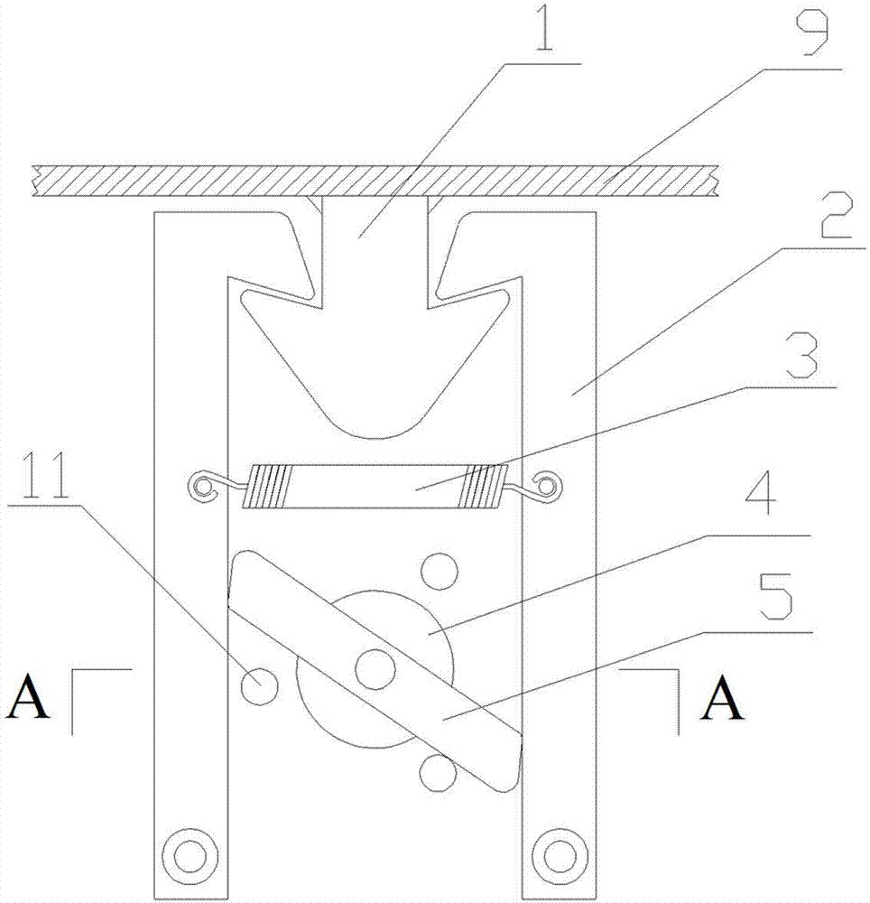
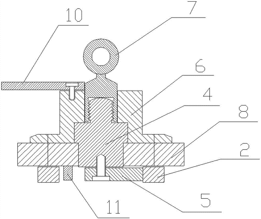
[0010] Such as figure 1 , 2 As shown, the anti-theft lock includes a lock pin 1, a lock core 4, and two symmetrically arranged lock hooks 2. The lock pin 1 is arranged in a triangle shape, and the two lock hooks 2 are respectively arranged facing inward and arranged between the two lock hooks 2. The two ends of the tension spring 3 and the tension spring 3 are respectively connected to the two lock hooks 2, the lock core 4 is arranged between the two lock hooks 2, and the inner end of the lock core 4 is fixedly connected to a transmission rod 5, the transmission rod 5 The two ends respectively abut against the two lock hooks 2, the lock pin 1 is arranged between the two lock hooks 2, a thread is provided on the outer side wall of the lock core 4, and a key 7 is threaded on the upper part of the lock core 4, A lock ring 6 is provided on the outer periphery of the lock cylinder 4, and the key 7 is arranged between the lock ring 6 and the lock cylinder 4. The outer top end of the ...


PUM


Abstract

The invention discloses an anti-theft lock and relates to the technical field of lock manufacture. The anti-theft lock comprises a lock pin, a lock core and two symmetrically distributed lock hooks, wherein the lock pin is arranged in a triangular mode, the two lock hooks are respectively arranged in inwards opposite mode, a tension spring is arranged between the two lock hooks, two ends of the tension spring are respectively connected onto the two lock hooks, the lock core is distributed between the two lock hooks, the inner end of the lock core is fixedly connected with a transmission rod, two ends of the transmission rod respectively butt against the two lock hooks, the lock pin is distributed between the two lock hooks in matching mode, threads are arranged on the lateral wall on the outer part of the lock core, a key is in thread connection with the upper portion of the lock core, a lock ring is arranged on the periphery of the lock core, and the key is distributed between the lock ring and the lock core. The anti-theft lock is simple in structure, convenient to use, easy to produce and manufacture, good in anti-theft effect and capable of being widely used in industrial doors of distribution boxes of street lamp posts, plants and the like.

Description

Technical field [0001] The invention relates to the technical field of manufacturing a lock. Background technique [0002] The existing anti-theft lock of the distribution box on the street lamp pole has a simple structure. It is directly composed of a lock cylinder and a lock plate. It is turned on and off by a rotating lock cylinder. The lock cylinder drives the lock plate to rotate through the lock plate and the lamp pole wall. In addition, the light pole anti-theft is directly blocked by an ordinary padlock. The simple lock mentioned above does not have a good anti-theft effect. Some locks with complex structures and good anti-theft effect are not suitable for street lamp poles. Anti-theft, and the use cost is also high. Summary of the invention [0003] The invention relates to an anti-theft lock, and aims to solve the defect that the existing light pole anti-theft lock has poor anti-theft effect. [0004] The present invention includes a lock pin, a lock core, and two symmet...

Claims


Application Information

Patent Timeline
Patent Type & Authority Applications(China)
IPC IPC(8): E05B65/52E05B15/00E05B17/00
Inventor 韩润喜
Owner 韩润喜
Why Eureka
Try Eureka