Engine Integrated Cooling System

A technology for engines and heat dissipation fans, which is applied in the direction of engine components, combustion engines, machines/engines, etc., and can solve the problems of unfavorable engine comprehensive heat dissipation, reduced engine efficiency, waste, etc.

Inactive Publication Date: 2017-06-13
TIANJIN SANTROLL ELECTRIC AUTOMOBILE TECH CO LTD
View PDF5 Cites 0 Cited by
  • Summary
  • Abstract
  • Description
  • Claims
  • Application Information

AI Technical Summary

Problems solved by technology

In the above device, the temperature of the heat dissipation module is controlled by controlling the air volume of the fan. Generally, one fan is used to dissipate heat from the intercooling system and the water cooling system at the same time, such as figure 1 As shown, because the target temperature required by the intercooler module and the radiator module of the water tank is different, for example, the target temperature of the water tank will be higher than the temperature of the intercooler module. When the temperature has reached the target temperature and there is no need for heat dissipation, when using the same fan for cooling, only the heat dissipation temperature can be set for the water tank or intercooler, which may cause unnecessary waste or reduce engine efficiency, which is not conducive to engine performance. Comprehensive heat dissipation

Method used


Image

  • Engine Integrated Cooling System
  • Engine Integrated Cooling System
  • Engine Integrated Cooling System

Examples


Embodiment 1

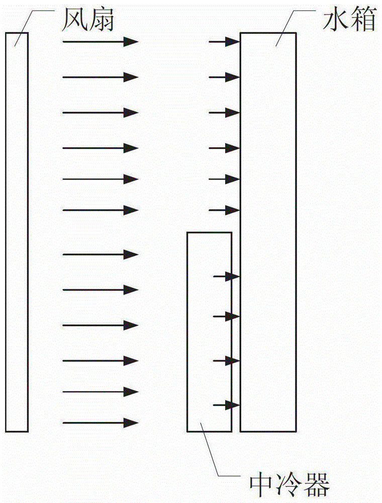
[0019] In this embodiment, the intercooler and the water tank are separately arranged. A fan system can be set for the two systems respectively. The target temperature t of the heat dissipation of the water tank preset in the fan controller 1 and the target temperature t of the intercooler 2 , the temperature detection device respectively detects the water temperature t 1 ’ and temperature t 2 ’ sent to the fan controller via the CAN bus. According to t 1 with t 1 ’, t 2 with t 2 ’ to calculate the appropriate fan speed. For example, when the detected temperature of the water tank or the intercooler has reached the target water temperature or air temperature, the fan controller located at the water tank or the intercooler judges that heat dissipation is not needed, and the water tank fan or the intercooler fan does not start; otherwise, the water tank fan or The intercooler fan is activated; if multiple fans are installed at the water tank or intercooler, the temperat...

Embodiment 2

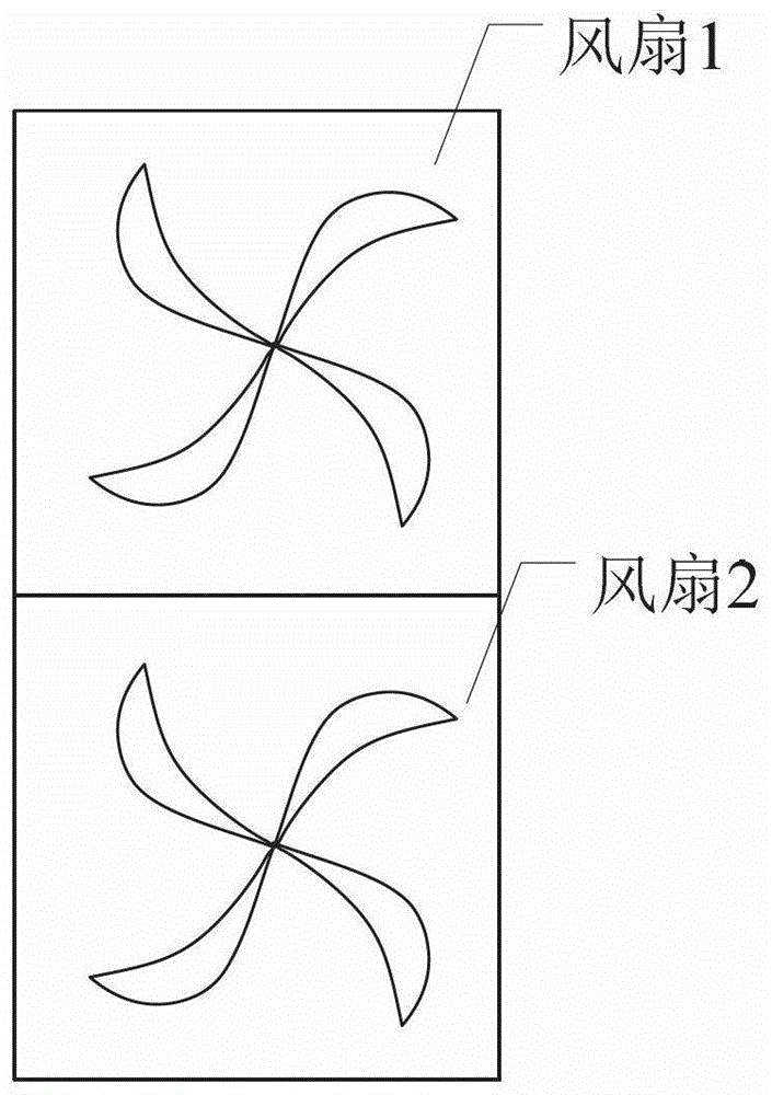
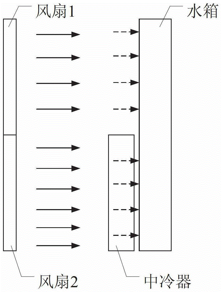
[0021] In this embodiment, the intercooler and the water tank are arranged overlappingly, such as image 3 shown. At this time, only one fan system can be set for the intercooler and the water tank, and the fan system is composed of fan 1 and fan 2, such as figure 2 shown. According to the comparison between the detected temperature of the intercooler and the water tank and the preset temperature, the fan is controlled to start and stop. The temperature detection device located in the water tank and the intercooler will set the water temperature t 1 ’ and temperature t 2 ’ are sent to each fan controller respectively, and the controller presets the target water temperature t 1 , the target temperature t 2 , if t 1 '> t 1 , then the fan group 1 located at the water tank starts, if the air temperature t 2 '> t 2 , located in the intercooler cooling fan group 2 to start, the cold air of fan 2 can also dissipate heat to the water tank after passing through the intercoole...


PUM


Abstract

The invention relates to a comprehensive heat removal system of an engine. The comprehensive heat removal system comprises a water tank, an intercooler and a fan system, wherein the fan system removes the heat of the intercooler and the water tank. The comprehensive heat removal system is characterized in that the fan system comprises two groups of fans that are totaled more than two; each fan is controlled by a fan controller to remove the heat of the water tank and the intercooler respectively; the water tank and the intercooler are arranged in an overlapped manner; and one group of fans remove the heat of the overlapped part of the water tank with the intercooler, and the other group of fans remove the heat of the non-overlapped part of the water tank. The comprehensive heat removal system of the engine disclosed by the invention can remove the heat of an intercooling heat removal system and a water cooling heat removal system respectively according to actual requirements, and the cooling efficiency of the comprehensive heat removal system is improved.

Description

technical field [0001] The invention relates to a cooling device, in particular to a cooling device for a vehicle engine. Background technique [0002] In traditional vehicles, the engine is generally used to drive the heat dissipation fan to cool the engine intercooler pipeline and the water tank heat dissipation pipeline. When the temperature of the engine cooling system reaches the target temperature, the engine is separated from the heat dissipation fan to control the start and stop of the fan. Although the structure and control method of this traditional radiator fan are relatively simple, it cannot meet the actual needs of engine cooling, and if the circulating coolant temperature of the engine is low, when there is no need to cool the circulating coolant, the fan motor cannot Accurate detection of the actual temperature of the engine cooling pipeline will result in waste of fuel. [0003] Chinese patent CN 10219189A discloses an integrated device for a vehicle engine...

Claims


Application Information

Patent Timeline
Patent Type & Authority Patents(China)
IPC IPC(8): F01P7/04F02B29/04
CPCY02T10/12
Inventor 高小二马学伟
Owner TIANJIN SANTROLL ELECTRIC AUTOMOBILE TECH CO LTD
Why Eureka
Try Eureka