Supercharge Your Innovation With Domain-Expert AI Agents!

Rack

A rack and pinion technology, applied to components with teeth, belts/chains/gears, portable lifting devices, etc., to achieve low manufacturing cost, large spindle size, and simple configuration

Inactive Publication Date: 2012-12-12
ROTO FR
View PDF5 Cites 0 Cited by
  • Summary
  • Abstract
  • Description
  • Claims
  • Application Information

AI Technical Summary

Problems solved by technology

To date no device is known by which different spindle sizes can be achieved while using the same drive pinion

Method used


Image

  • Rack
  • Rack
  • Rack

Examples


Embodiment Construction

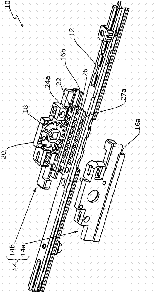
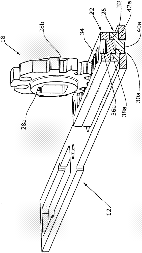
[0025] figure 1 A drive rod fitting 10 according to the invention is shown for actuating locking elements of a door leaf (not shown). The transmission rod fitting 10 has a transmission rod 12 and a drive housing 14 . The drive housing 14 comprises two drive housing parts 14a, 14b. The drive housing parts 14 a , 14 b each have guide projections 16 a , 16 b which engage behind the drive rod 12 in order to guide the drive rod 12 in the drive housing 14 . The drive rod fitting 10 also has a drive pinion 18 . The drive pinions 18 are guided in respective recesses (not shown) of the drive housing parts 14a, 14b. The drive pinion 18 has an essentially quadrangular spindle recess 20 for a spindle with a rectangular cross section connected to an actuating element (not shown). The spindle notch 20 represents the axis of rotation of the drive pinion 18 . Thus, manipulation of the manipulation element connected to one spindle causes the drive pinion 18 to rotate.

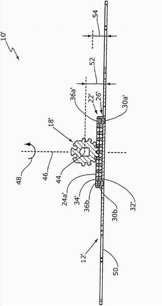
[0026] Rotation o...


PUM


Abstract

The invention relates to a rack (22') used for driving rod accessories (10'). The top (34') of the rack is provided with at least a plurality of driver grooves (24a') used for embedding a drive pinion (18'). The below (32') opposite to the top (34') of the rack (22') is provided with at least one first joint device (30a', 30b). The at least one first joint device is used for jointing the rack (22') with a transmission bar (12') of the driver rod accessories (10') or another rack (26').

Description

technical field [0001] The invention relates to a toothed rack for a drive rod fitting, which has at least on its upper side a plurality of drive grooves for engaging a drive pinion. Background technique [0002] It is known to provide a window or door leaf with a transmission rod fitting for controlling the locking elements of said leaf. In this case, a drive rod of the drive rod fitting is moved by a drive pinion, which engages in the respective drive grooves of the drive rod. The drive pinion is rotated via a spindle, which is connected, for example, to an actuating element, such as a handle. The dimension between the center of rotation of the drive pinion and the underside of the transmission rod is called the arbor dimension. The mandrel size is typically between 11mm and 15mm. The arbor dimensions have hitherto been precisely determined for each transmission rod fitting. If different spindle sizes are required on one fan, it is not possible to simply use drive pini...

Claims


Application Information

Patent Timeline
Patent Type & Authority Applications(China)
IPC IPC(8): F16H55/26
CPCE05C9/021E05B63/0056
Inventor P·施塔普夫P·米尼希T·尼柯斯L·马顿
Owner ROTO FR
Features
  • R&D
  • Intellectual Property
  • Life Sciences
  • Materials
  • Tech Scout
  • Unparalleled Data Quality
  • Higher Quality Content
  • 60% Fewer Hallucinations
Learn More