
Electric heating system for fluid transportation pipe and pipe assembled with electric heating system

A technology for transportation pipes and heating systems, which is applied in the direction of electric heating devices, piping systems, transportation and packaging, etc., and can solve the problems of rising overall risks

Inactive Publication Date: 2012-12-12
ITP
View PDF10 Cites 7 Cited by
  • Summary
  • Abstract
  • Description
  • Claims
  • Application Information

AI Technical Summary

Problems solved by technology

Multiplication of wires and segments results in multiplication of pipe lengths, which in turn results in systems containing tens of thousands of connections, increasing overall risk to unacceptable levels

Method used


Image

  • Electric heating system for fluid transportation pipe and pipe assembled with electric heating system
  • Electric heating system for fluid transportation pipe and pipe assembled with electric heating system
  • Electric heating system for fluid transportation pipe and pipe assembled with electric heating system

Examples


Embodiment Construction

[0056] Now, the present invention will be specifically described.

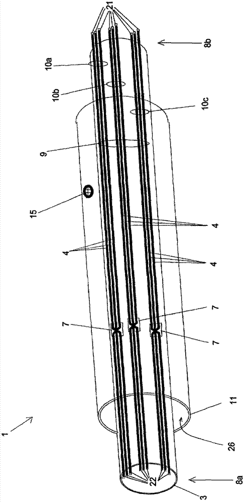
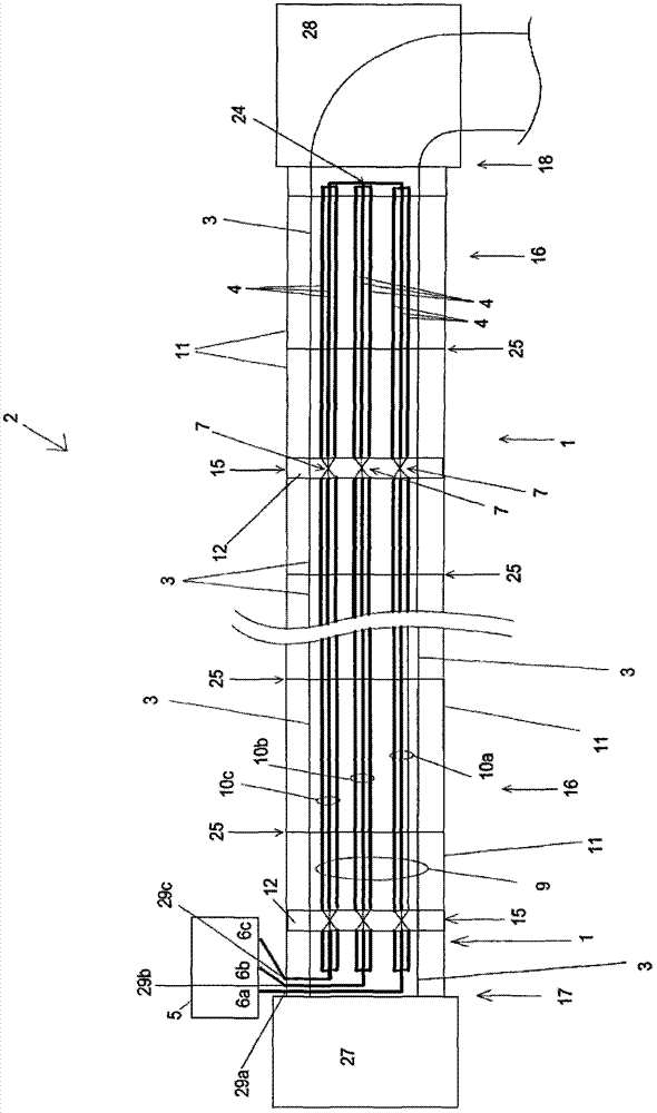
[0057] figure 1 Section 1 is shown assembled with other sections to form a pipe 2 for transporting fluids such as hydrocarbons. This section comprises a first casing 3, or inner casing, through which the fluid to be transported flows.

[0058] The second bushing 11 is arranged around the first bushing 3 and keeps a certain distance therefrom. The bushing 3 and the bushing 11 delimit an annular region 26 . The annular area 26 accommodates, for example, the heating system and the thermal insulation of the first sleeve 3 . The first sleeve 3 can be made of metal, and the second sleeve 11 can also be made of metal. The first casing 3 and the second casing 11, for example, can be made of steel or other metals. The second bushing 11 is explicitly shown to show the heating system, no insulation is shown in figure 1 middle.

[0059] A tube provided with a single sleeve could conceivably have a heating wire pres...


PUM


Abstract

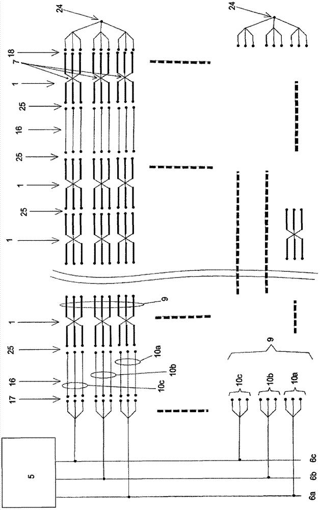
The invention relates to an electric heating system for at least one section (1) fluid transportation pipe (2). The pipe includes a sleeve (3) for flowing fluid to-be-transported. The heating system includes a wire (4) supplied by power through connecting elements (21 and 22) and arranged around the sleeve (3). The power includes a plurality of phases. In the heating system, the wire (4) is a set (9) of multiple groups (10a, 10b and 10c), wherein each group includes a plurality of wires (4). Each group in the set can be supplied by different phases. The electric system includes a connection unit (7) for electric connection and connecting each group of wire together.

Description

technical field [0001] The technical scope of the present invention is: the heating system of the fluid transport pipe. In particular, the invention relates to long-distance subsea or land transportation of hydrocarbons. Background technique [0002] For the transport of fluids in cold environments, for example, subsea transport of hydrocarbons, the technical solution consists in heating the pipes to avoid the formation of obstructions by the cooling of the fluid. Therefore, a minimum temperature must be maintained by heating the transport tube. Electric heating can solve this problem. [0003] The robustness of the heating equipment must be suitable for the environmental conditions in which the transport pipe is located. Subsea hydrocarbon transport pipelines can be located to depths of several kilometers so that it is difficult to perform any maintenance operations on these pipelines. The same difficulty arises with onshore pipelines laid in harsh environments. [000...

Claims


Application Information

Patent Timeline
Patent Type & Authority Applications(China)
IPC IPC(8): F16L53/00F16L53/34F16L53/38
CPCH05B2203/016H05B6/56H05B3/56Y02E60/34F16L53/004F16L53/008F17D1/18H05B1/0244H05B3/42H05B6/06H05B6/108H05B2214/03F16L53/34F16L53/38Y10T29/49117Y10T137/6606F16L53/35F16L1/16F16L53/00H05B3/40
Inventor 克里斯蒂安·格尔森
Owner ITP
Learn More