Heat tube

A heat pipe and metal pipe technology, applied in the field of heat conduction, can solve the problems of low heat conduction efficiency of the heat pipe, easy detachment of the capillary structure of the heat pipe, etc., and achieve the effects of good ductility and processing performance, shortening processing time, and improving efficiency.

Inactive Publication Date: 2012-12-12
ZHONGSHAN WEIQIANG TECH
View PDF5 Cites 4 Cited by
  • Summary
  • Abstract
  • Description
  • Claims
  • Application Information

AI Technical Summary

Problems solved by technology

[0005] The purpose of the present invention is to provide a heat pipe, which aims to solve the problems of the capillary structure of the existing heat pipe that is easy to fall off and the heat conduction efficiency of the heat pipe is low.

Method used


Image

  • Heat tube
  • Heat tube
  • Heat tube

Examples


Embodiment Construction

[0026] In order to make the object, technical solution and advantages of the present invention clearer, the present invention will be further described in detail below in conjunction with the accompanying drawings and embodiments. It should be understood that the specific embodiments described here are only used to explain the present invention, not to limit the present invention.

[0027] The specific realization of the present invention is described in detail below in conjunction with specific embodiment:

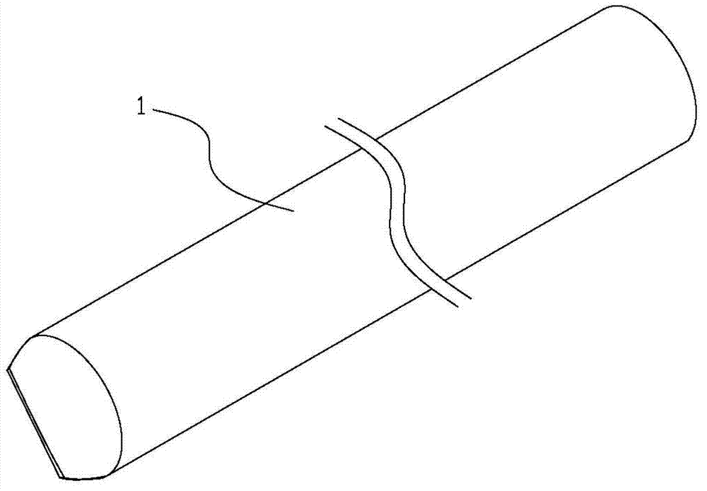
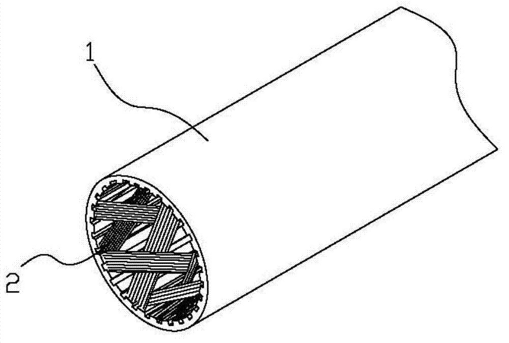
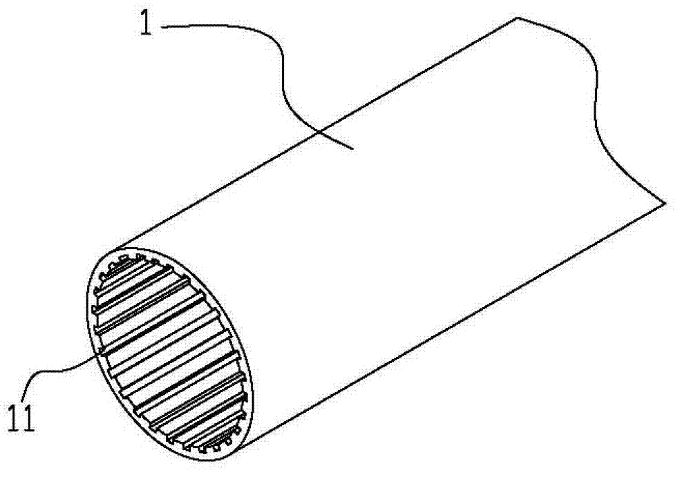
[0028] see Figure 1~4 , the heat pipe mainly includes a metal pipe 1, a metal mesh 2 and an elastic member 3, and the three are sequentially socketed from outside to inside. Among them, the metal pipe 1 is a hollow structure with both ends sealed, which is filled with working fluid, and a plurality of grooves 11 are provided on the inner wall of the metal pipe 1, and the plurality of grooves 11 extend along the length direction of the metal pipe 1, and its function is ...


PUM

PropertyMeasurementUnit
diameteraaaaaaaaaa

Abstract

The invention provides a heat tube which comprises a metal tube, wherein the metal tube is sealed in two ends and is hollow; a work fluid is filled in the metal tube; a plurality of grooves extending along the length direction of the metal tube are formed in the inner wall of the metal tube; a metal net formed by mutually intersecting and knitting a plurality of metal bundles is sleeved in the metal tube; the metal net is formed by arranging a plurality of metal wires in parallel; and an elastic part is sleeved in the mesh net and applies an outward elastic force to the metal net, so that the mesh net is tightly attached to the inner wall of the metal tube. According to the heat tube disclosed by the invention, each metal bundle of the metal net is formed by arranging a plurality of metal wires in parallel; a plurality of fine groove grains formed by treating are formed on all or part of metal wires of each metal bundle; and the fine groove grains extend along the length direction of the metal wires. Each metal bundle contains a plurality of metal wires, so that reflowing channels of the metal bundle are increased; and particularly, the fine groove grains are formed on the metal wires, so strong hydrophilicity and water retention property can be realized, and the dry combustion can be avoided.

Description

technical field [0001] The invention belongs to the technical field of heat conduction, and in particular relates to a heat pipe. Background technique [0002] The heat pipe can rely on the phase change of its internal working liquid to realize rapid heat conduction, has extremely high heat conduction efficiency, and is widely used in various fields that require efficient heat dissipation. [0003] A conventional heat pipe is mainly a closed metal tube with a groove in the tube and a capillary sintered structure near the groove, and an appropriate amount of working fluid is injected into the tube. When used with a heat source, the heat of the heat source is transferred to one end of the heat pipe, and the working fluid in the pipe absorbs heat and vaporizes. The steam flows to the other end of the heat pipe at a high speed under the action of the pressure difference, and releases latent heat after encountering the cold source. Under capillary action, the groove and capillar...

Claims


Application Information

Patent Timeline
Patent Type & Authority Applications(China)
IPC IPC(8): F28D15/04
CPCF28D15/046
Inventor 李克勤
Owner ZHONGSHAN WEIQIANG TECH
Why Eureka
Try Eureka