
Infrared array type camera

A camera and array technology, applied in the field of cameras, can solve problems such as long viewing distance, and achieve the effect of uniform image without dark, less snowflakes and high definition

Inactive Publication Date: 2012-12-12
毛振刚
View PDF0 Cites 2 Cited by
  • Summary
  • Abstract
  • Description
  • Claims
  • Application Information

AI Technical Summary

Problems solved by technology

[0005] The purpose of the present invention is to provide an infrared array camera with high definition, long service life, less snowflakes, uniform image without vignetting and long visual distance for the deficiencies of existing infrared night vision cameras.

Method used


Image

  • Infrared array type camera

Examples


Embodiment Construction

[0017] Embodiments of the present invention are described in further detail below in conjunction with the accompanying drawings:

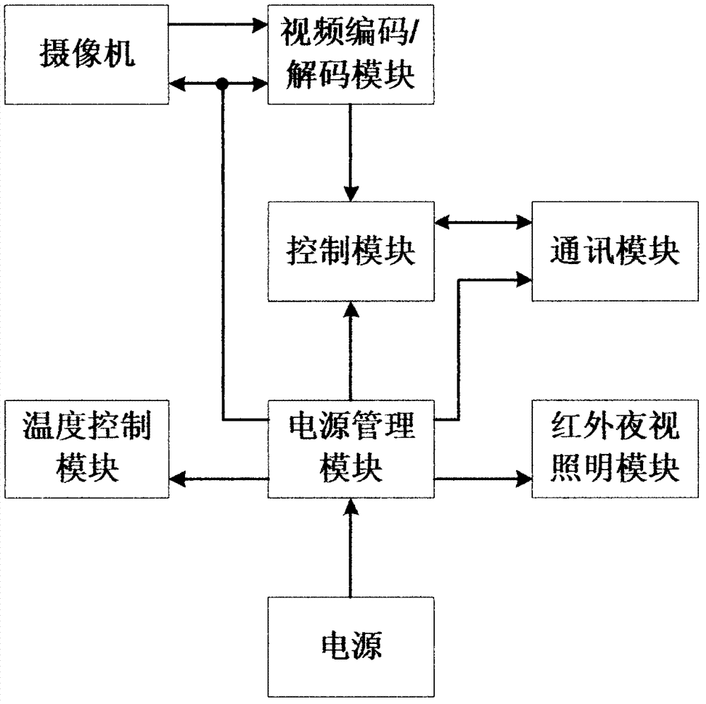
[0018] An infrared array camera, such as figure 1 As shown, it consists of camera, video encoding / decoding module, control module, communication module, power management module, temperature control module, infrared night vision lighting module, power supply and so on. The camera is connected to the input end of the video encoding / decoding module, the output end of the video encoding / decoding module is connected to the input end of the control module, the output end of the control module is connected to the communication module, and the power supply supplies power to other modules through the power management module. The video signal captured by the camera is decoded by the video encoding / decoding module, and the control module controls the communication module to transmit the signal to the receiving end. The temperature control module is equipped ...


PUM


Abstract

The invention relates to an infrared array type camera which comprises a camera, a video coding / decoding module, a control module, a communication module, a power management module, a temperature control module, an infrared night vision lighting module, a power supply and the like. The camera is connected with an input end of the video coding / decoding module, an output end of the video coding / decoding module is connected with an input end of the control module, an output end of the control module is connected with the communication module, and the power supply is used for supplying power to all other modules through the power management module. The infrared array type camera is capable of achieving automatic temperature adjustment.

Description

technical field [0001] The invention belongs to the technical field of cameras, in particular to an infrared array camera. Background technique [0002] Active semiconductor infrared technology was first successfully developed by Bell Laboratories in the United States in the early 1960s. The earliest infrared conversion efficiency was only 5%, which was very low. It was mostly used in simple products such as infrared remote controls. After repeated practice and development in night vision applications, by combining a single infrared LED package and fixing it around the lens, it can actively supplement the light for the surveillance camera. The effective efficiency of a single LED infrared diode is about 20%, but there are obvious defects, that is, the luminous power is greatly reduced due to the heat dissipation treatment, so that the illumination distance is reduced sharply, and the nominal illumination distance is often not reached; One is that the volume of the product i...

Claims


Application Information

Patent Timeline
Patent Type & Authority Applications(China)
IPC IPC(8): H04N5/225G03B15/03
Inventor 毛振刚
Owner 毛振刚
Learn More