Connector structure for device connection

A connector and contact board technology, which can be used in electrical devices, vehicle connectors, components of connecting devices, etc., can solve problems such as cost increase

Active Publication Date: 2012-12-12
YAZAKI CORP
View PDF6 Cites 5 Cited by
  • Summary
  • Abstract
  • Description
  • Claims
  • Application Information

AI Technical Summary

Problems solved by technology

Therefore, problems may arise as follows: cost increases; bolts and nuts are required to connect the terminals to each other; troublesome work for fastening the bolts is required; fit tolerances between, so an alignment mechanism is required

Method used


Image

  • Connector structure for device connection
  • Connector structure for device connection
  • Connector structure for device connection

Examples


Embodiment Construction

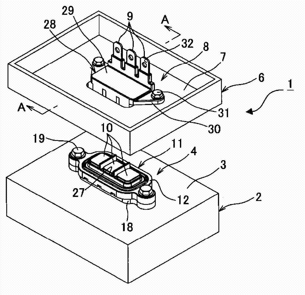
[0055] Figure 1 to Figure 3 A connector structure for device connection according to a first embodiment of the present invention is shown.

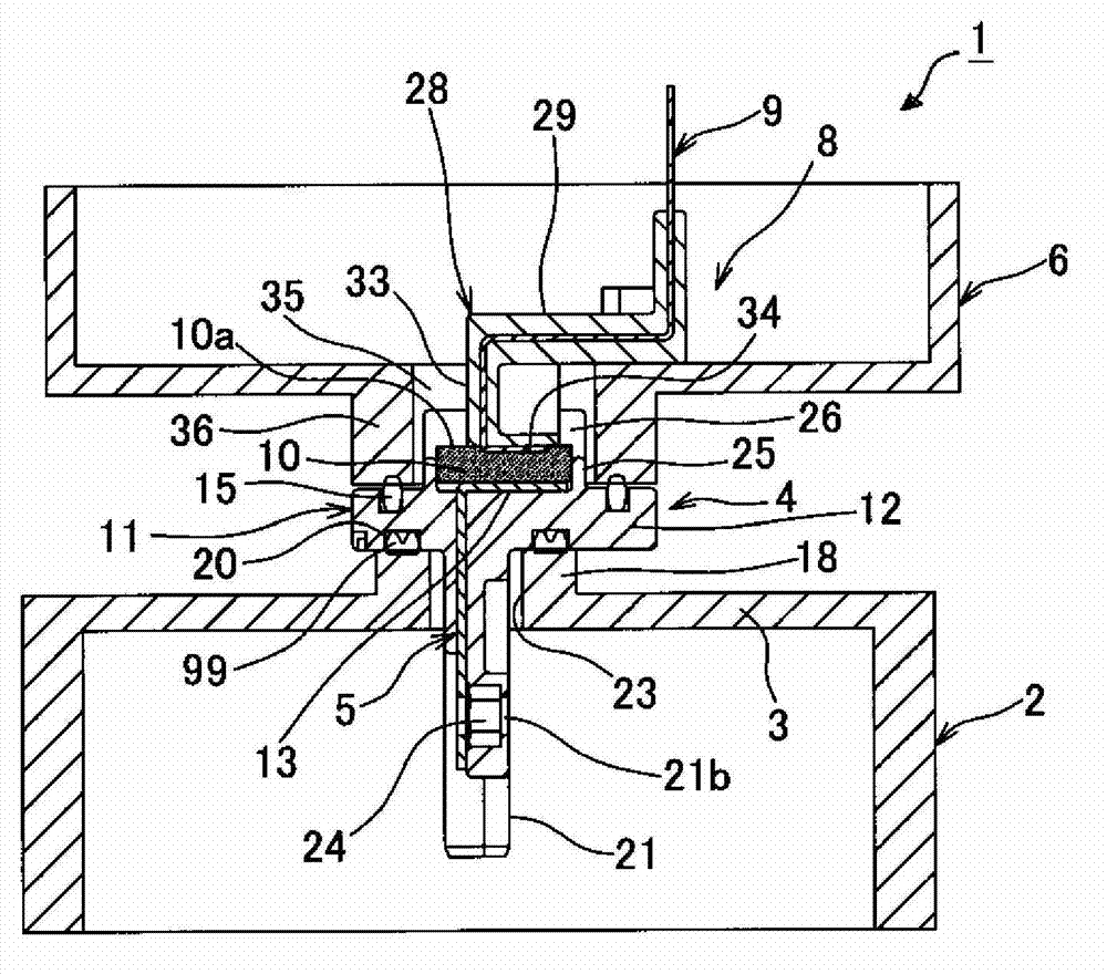
[0056] Such as figure 1 As shown in , such a connector structure 1 for device connection is configured such that: a motor-side connector 4 (a connector) to terminal 5 (see figure 2 ) with the terminals 9 of another connector 8 mounted directly on the lower wall 7 of the shell 6 made of conductive metal of the inverter (another device), in image 3 While the shells 2 and 6 of the two devices shown in figure 2 ) while connected to each other.

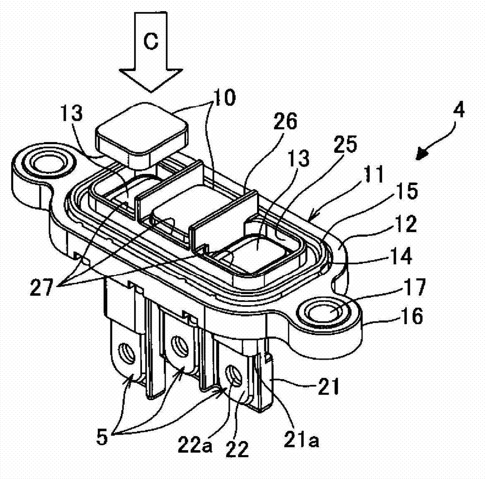
[0057] Such as figure 2 As shown in , the motor side connector 4 includes: a case (also referred to as a terminal block) 11 made of insulating resin; three L-shaped plate-shaped terminals 5 arranged in the case 11 and made of conductive metal formed; a rectangular conductive rubber 10 juxtaposed on a part of the upper wall 12 of the housing 11 and in contact with the upper surface of each hor...


PUM


Abstract

Good connections of connectors for devices are made with terminals using conductive rubber. A connector structure for device connection (1, 61) comprises one connector (4, 59) provided on one device case (2, 57) and another connector (8, 68) provided on another device case (6, 66). The one connector (4, 59) is provided with an insulating housing (11, 64) having a plurality of recessed receiving parts (27, 77) in a line, terminals (5, 65) having contact plate parts (13, 82) accommodated in the recessed receiving parts, and conductive rubber (10) in contact with the contact plate parts and accommodated in the recessed receiving parts. The other connector (8, 68) is provided with other terminals (9, 70) having contact plate parts (34, 91) to be inserted in contact with the conductive rubber when the two cases are affixed, and another insulating housing (28, 69) that accommodates the other terminals.

Description

technical field [0001] The present invention relates to a connector structure for device connection used in the case of connecting terminals of connectors of devices such as, for example, a motor, an inverter, etc. in an electric vehicle or the like to each other via conductive rubber . Background technique [0002] In the past, for example, as a device-directly-mounted connector structure used in the case where devices such as a motor, an inverter, etc. , a connector in which three L-shaped plate-shaped terminals are juxtaposed therein is fixed to a housing of a device by fastening with bolts, and a connector in which three substantially L-shaped plate-shaped terminals are juxtaposed therein is fixed by fastening with bolts While the case fixed to another device, four positioning pins for aligning the connectors are provided on one case, positioning holes to engage the positioning pins inserted therein are provided on the other case, and on the other case, While positioni...

Claims


Application Information

Patent Timeline
IPC IPC(8): H01R13/22
CPCH01R24/68H01R2105/00B60L3/0069H01R13/2414H01R2201/26H01R24/76
Inventor 田中雅宏加藤元
Owner YAZAKI CORP
Why Eureka
Try Eureka