Rotary tiller with automatic clutch device

An automatic clutch and rotary tiller technology, which is applied in the field of rotary tillers, can solve problems such as hidden dangers in operation safety, operation accidents, and operational errors, and achieve the effects of good automation, elimination of hidden safety hazards, and accurate and reliable control

Active Publication Date: 2012-12-19
湖南湘源金穗智能装备有限公司
View PDF6 Cites 5 Cited by
  • Summary
  • Abstract
  • Description
  • Claims
  • Application Information

AI Technical Summary

Problems solved by technology

But there are still two deficiencies in this technical solution: the one is that the rotation and stop control of the belt clutch wheel is not good for the rotary cultivator.
During rotary tillage operations, it is often necessary to lift the working position of the rotary tiller in the rotary tiller. The belt clutch wheel is set on the rotary tiller, and it will change the working position following the lifting movement of the rotary tiller. When the working position of the rotary tiller rises from the low position When it reaches a high position, the clutch seat in the belt clutch wheel will rotate correspondingly, and the mutual positional relationship between the clutch pawl and the clutch seat will change due to triggering, causing the working state of the belt clutch wheel to change, and the power input that has been cut off may re-enter In the semi-engaged or engaged state, the rotary blade will re-enter the rotating state, and the accidental rotation of the rotary blade will bring serious safety hazards to the operation
The second is that the operation procedure is complicated. The operator not only needs to manipulate the clutch mechanism of the belt clutch wheel to engage or cut off the power input of the rotary tiller, but also needs to manipulate the lifting mechanism of the rotary tiller to lift the working position of the rotary tiller in the rotary tiller. , the two operations are difficult to cooperate, and it is easy to make operation errors and cause operation accidents

Method used


Image

  • Rotary tiller with automatic clutch device
  • Rotary tiller with automatic clutch device
  • Rotary tiller with automatic clutch device

Examples


Embodiment Construction

[0012] Below, the specific implementation manners of the present invention will be further described in conjunction with the accompanying drawings.

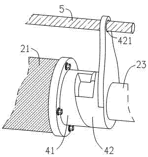
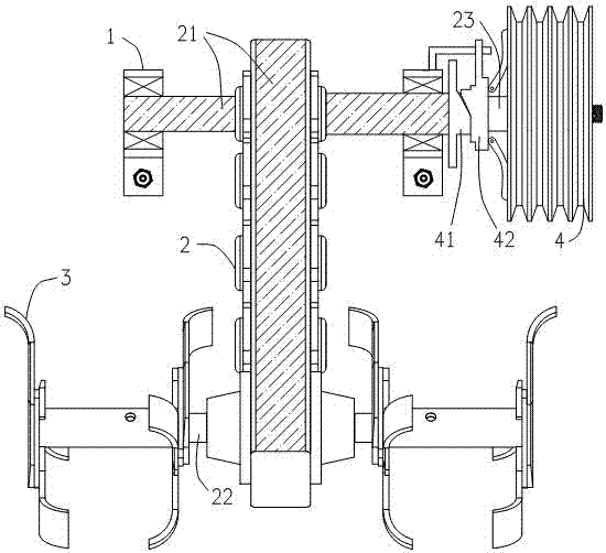
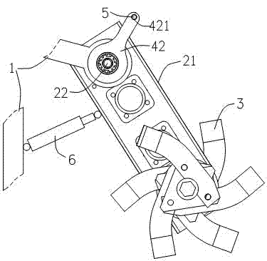
[0013] figure 1 It shows an embodiment of a rotary tiller with an automatic clutch device, including a liftable rotary tiller connected to the frame 1, and the rotary tiller includes a transmission box 2 and a rotary tiller installed on the output shaft 22 of the transmission box 2. Knife 3, transmission box 2 box body 21 is movable and hinged on the frame 1 with the transmission box 2 input shaft 23 as the axis, and the lifting mechanism is connected to the transmission box 2 box body 21, which can push the transmission box 2 box body 21 to rotate around the hinge axis With the working position of lifting rotary tiller 3; belt clutch wheel 4 is set on the transmission box 2 input shaft 23, and the separation seat 41 in the belt clutch wheel 4 is fixed on the transmission box 2 casing 21, and the separation claw in the belt clutc...


PUM


Abstract

The invention relates to a rotary tiller with an automatic clutch device. The rotary tiller comprises a lifting rotary tilling device which is connected onto a rack. The rotary tilling device comprises a transmission case and a rotary tilling blade which is installed on the output shaft of the transmission case. A transmission case body is movably hinged on the rack by taking the input shaft of the transmission case as an axis. A lifting mechanism is connected with the transmission case body and can push the transmission case body to rotate around the hinge axis, so as to lift the rotary tilling blade to change the working position of the rotary tilling blade. A belt clutch wheel is arranged on the input shaft of the transmission case. A declutch seat in the belt clutch wheel is fixedly arranged on the transmission case body. A declutch claw in the belt clutch wheel is axially and movably fixed on the rack. Since the declutch claw of the belt clutch wheel is axially and movably fixed on the rack, the declutch claw always does not rotate and the working state of the belt clutch wheel is changed only through the magnitude of the rotating angle of the declutch seat which rotates with the transmission case body, the accurate and reliable control on the rotating and stopping states of the rotary tilling device can be realized and the potential safety hazard that the rotary tilling blade accidentally rotates is eliminated; and the automatic clutch function of the rotary tilling device is realized and the rotary tiller is enabled to have the characteristics of simplicity and convenience in operation and high automation level.

Description

technical field [0001] The invention relates to an agricultural soil preparation machine, in particular to a rotary cultivator with an automatic clutch device. Background technique [0002] The known rotary cultivator includes a traveling mechanism, a power machine and a liftable rotary cultivator installed at the rear end of the frame. The power input shaft of the rotary cultivator is generally provided with a belt clutch wheel, and the power machine directly drives the belt clutch wheel through the belt. The belt clutch wheel It can engage or cut off the power input to realize the rotation and stop control of the rotary tiller to meet the operation needs. But still there are two deficiencies in this technical scheme: the one, the belt clutch pulley is bad to the rotation stop control of rotary cultivator. During rotary tillage operations, it is often necessary to lift the working position of the rotary tiller in the rotary tiller. The belt clutch wheel is set on the rotar...

Claims


Application Information

Patent Timeline
Patent Type & Authority Applications(China)
IPC IPC(8): A01B71/06
Inventor 李源湘胡华锋
Owner 湖南湘源金穗智能装备有限公司
Why Eureka
Try Eureka