Semiautomatic laser pipe cutting machine
A pipe cutting machine, semi-automatic technology, applied in the direction of laser welding equipment, welding equipment, metal processing equipment, etc., can solve the problems of error, product quality decline, low labor efficiency, etc., achieve accurate and stable positioning, improve production efficiency, reduce The effect of worker labor intensity
- Summary
- Abstract
- Description
- Claims
- Application Information
AI Technical Summary
Problems solved by technology
Method used
Image

Examples
Embodiment
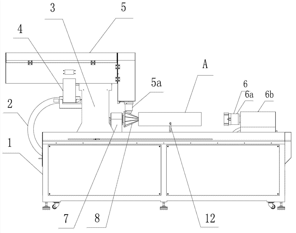
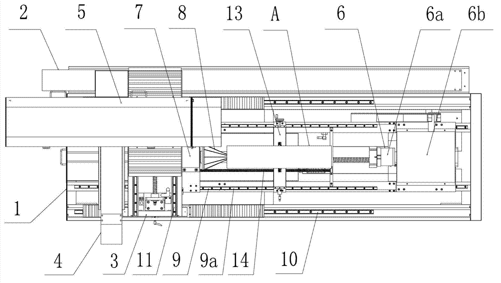
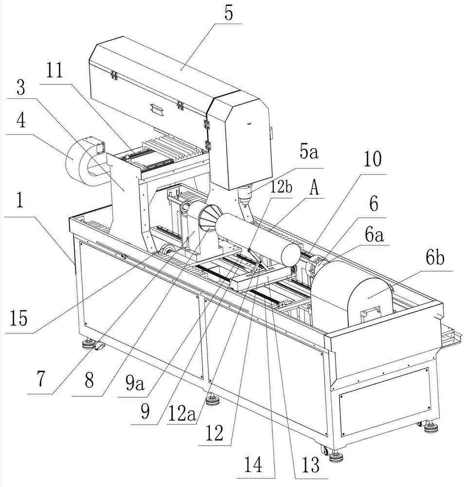
[0028] Example: Combine Figure 1 to Figure 5 As shown, the semi-automatic laser pipe cutting machine provided by the present invention has a frame 1, and the frame 1 is provided with a laser automatic cutting device and a pipe fixing device, wherein: the laser automatic cutting device has an X-axis The gantry 3 of the travel driving device 2 and the laser cutting device 5 arranged on the gantry 3 by the Y-axis traverse driving device 4, the X-axis and the Y-axis constitute a horizontal Cartesian coordinate system; The clamping device and the rotary pneumatic chuck 6 arranged oppositely to the traveling direction of the X-axis of the gantry 3 below the laser cutting device 5 , and the pipe support device arranged between the clamping device and the rotary pneumatic chuck 6 are jointly formed.
[0029] The rotary pneumatic chuck 6 described in this embodiment is a prior art, which is composed of a four-jaw pneumatic chuck 6a and a rotary cylinder 6b connected to and driving ...
PUM
 Abstract
Description
Claims
Application Information
 - Generate Ideas
- Intellectual Property
- Life Sciences
- Materials
- Tech Scout
- Unparalleled Data Quality
- Higher Quality Content
- 60% Fewer Hallucinations
Browse by: Latest US Patents, China's latest patents, Technical Efficacy Thesaurus, Application Domain, Technology Topic, Popular Technical Reports.
© 2025 PatSnap. All rights reserved.Legal|Privacy policy|Modern Slavery Act Transparency Statement|Sitemap|About US| Contact US: help@patsnap.com