Curve rotating platform device
A technology of rotating platforms and curves, applied in the field of structural design of rotating platforms, can solve the problems of monotonous and rigid building shapes, limiting the diversity of building shapes, unfavorable site scientific layout, etc.
- Summary
- Abstract
- Description
- Claims
- Application Information
AI Technical Summary
Problems solved by technology
Method used
Image
Examples
Embodiment 1
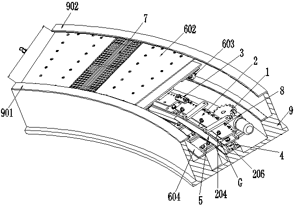
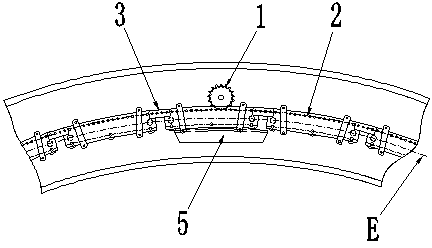
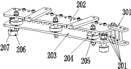
[0106] A kind of curved rotating platform device (see figure 1 , 12 ), the curved rotating platform device includes the following components: chain pin wheel transmission, loading platform 6 and sliding row device 7; the chain pin wheel transmission includes 20 pin wheel units, and between each pin wheel unit Sequential hinges form a closed chain structure; each loading platform 6 is fixed on a pin wheel unit, and two adjacent loading platforms 6 are connected together in a manner that allows relative swinging movements; two adjacent loading platforms 6 The two loading platforms 6 are connected together by the sliding device 7, and the two sides of the sliding device 7 are respectively connected and fixed on the adjacent two loading platforms 6, and the sliding device 7 allows the adjacent loading platforms 6 The swing changes its load-bearing plane.
[0107] All the loading platforms 6 and sliding row devices 7 in the curved rotary platform device form a curved rotary platf...
Embodiment 2
[0155] The content of this embodiment is mostly the same as that of Embodiment 1, and its difference mainly lies in:
[0156] 1) The chain pin wheel transmission device of the curved rotary platform device contains 50 pin wheel units, and the pin wheel units are sequentially hinged to form a closed chain structure (see figure 1 , see Figure 13 );
[0157] 2) The running path E is a gourd-shaped closed path composed of three arcs (two of which are the same) and a partial ellipse sequentially connected smoothly; the minimum arc radius in the running path E is the minimum turning radius R1 and the main tooth span M The ratio is R1 / M=2.24; according to the characteristics of the running path E, two identical arcs are used as the driving section F; the gear 1 and the corresponding balance beam 5 are set in the middle of the driving section F.
[0158] 3) The chain pin wheels in the curved rotary platform device meet the following requirements:
[0159] The ratio between the len...
Embodiment 3
[0172] The content of this embodiment is mostly the same as that of Embodiment 1, and its difference mainly lies in:
[0173] 1) The chain-type pin-wheel transmission device of the curved rotating platform device includes 100 pin-wheel units, and each pin-wheel unit is sequentially hinged to form a closed chain structure.
[0174] 2) The operating path E is a triangular closed path with rounded chamfers composed of three circular arcs and three straight lines connected sequentially and smoothly; the ratio of the minimum arc radius in the operating path E, that is, the minimum turning radius R1 to the main tooth span M is R1 / M=2.02;
[0175] In this embodiment, according to the characteristics of the running path E, the driving section F is set on three straight lines; the gear 1
[0176] Correspondingly there are three balance beams 5, which are distributed in the middle of the three linear drive sections F (see Figure 5 ).
[0177] 3) The chain pin wheels in the curved r...
PUM
| Property | Measurement | Unit |
|---|---|---|
| Tooth pitch | aaaaa | aaaaa |
| Diameter size | aaaaa | aaaaa |
| Diameter size | aaaaa | aaaaa |
Abstract
Description
Claims
Application Information
 - R&D
- Intellectual Property
- Life Sciences
- Materials
- Tech Scout
- Unparalleled Data Quality
- Higher Quality Content
- 60% Fewer Hallucinations
Browse by: Latest US Patents, China's latest patents, Technical Efficacy Thesaurus, Application Domain, Technology Topic, Popular Technical Reports.
© 2025 PatSnap. All rights reserved.Legal|Privacy policy|Modern Slavery Act Transparency Statement|Sitemap|About US| Contact US: help@patsnap.com


