Clamping piece lifting mechanism

A lifting mechanism and clip technology, applied in the direction of lifting devices, etc., can solve the problems of low safety and reliability of actions, poor running stability, etc.

Active Publication Date: 2012-12-19
SHANGHAI ZHILIAN PRECISION MACHINERY
View PDF6 Cites 6 Cited by
  • Summary
  • Abstract
  • Description
  • Claims
  • Application Information

AI Technical Summary

Problems solved by technology

[0003] The purpose of the present invention is to provide an improved clip lifting mechanism, which can overcome the shortcomings of poor running stability and low safety and reliability of the action in the prior art.

Method used


Image

  • Clamping piece lifting mechanism
  • Clamping piece lifting mechanism

Examples


Embodiment Construction

[0008] The present invention will be further described below in conjunction with the accompanying drawings and embodiments.

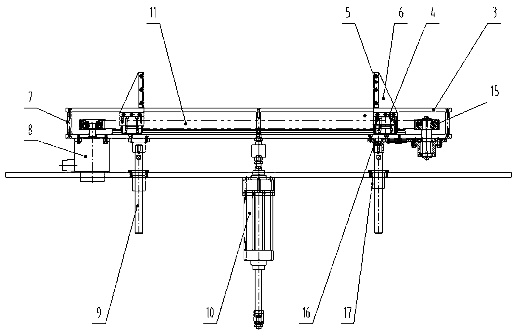
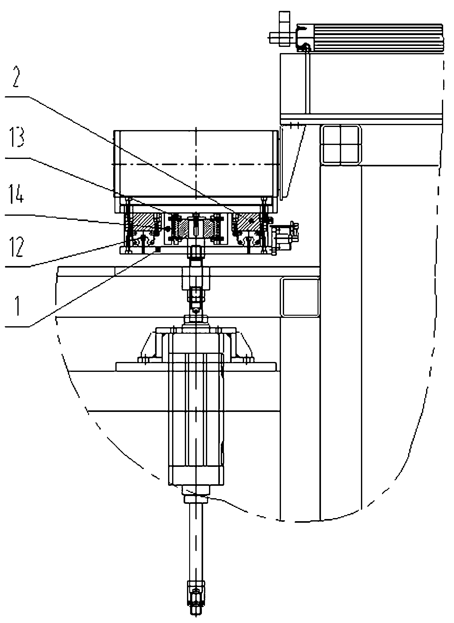
[0009] The present invention mainly comprises frame, and is located on the servomotor 8 on the frame, and its difference with the prior art is: the frame is provided with elevating device, and elevating device is set up with clip lifting platform. The clip lifting mechanism moves up and down relative to the frame under the influence of the cylinder, and the lifting guide rod guides the movement of the cylinder, which can enhance the smoothness and stability of this movement.

[0010] Lifting device is made of cylinder 10 and the elevating guide rod 9 that is located at both sides of cylinder respectively, and elevating guide rod is inserted in the linear bearing seat 17, and links to each other with clip lifting platform by guide rod seat 16. The clip lifting platform is composed of the rigid frame part of the clip lifting platform, the moving guide rai...


PUM


Abstract

The invention relates to a clamping piece lifting mechanism which is characterized in that a lifting device is arranged on a machine frame; and a clamping piece lifting platform is arranged on the lifting device. When in use, a bag clamping subassembly is relatively moved under the pulling of a synchronous belt, and finally a plurality of paper diapers on a bag conveying plate can be clamped; the conveying plate is raised through a cylinder; when the paper diapers are pushed to separate from the bag conveying plate through a pushing device, the cylinder is started to lower down to restore the bag conveying plate to an initial position for waiting for the next action. The whole mechanism is stable in running and safe and reliable in acting; the number of the diapers to be bagged can be adjusted; and the clamping piece lifting mechanism can meet various requirements on bagged diapers.

Description

technical field [0001] The invention relates to the technical field of lifting mechanisms, in particular to a clip lifting mechanism used in the production line of diapers. Background technique [0002] At present, during the operation of the clip lifting mechanism on the existing diaper assembly line, there are often situations in which the running stability is poor and the number of clips cannot be guaranteed. There is a problem of inaccurate positioning, which makes the subsequent processes on the assembly line unable to run normally. Contents of the invention [0003] The object of the present invention is to provide an improved clip lifting mechanism, which can overcome some shortcomings of poor running stability and low safety and reliability of action in the prior art. [0004] In order to achieve the above object, the technical solution of the present invention is: a clip lifting mechanism, which mainly includes a frame, and a servo motor installed on the frame, a...

Claims


Application Information

Patent Timeline
Patent Type & Authority Applications(China)
IPC IPC(8): B66F11/00
Inventor 周国红夏宝印
Owner SHANGHAI ZHILIAN PRECISION MACHINERY
Why Eureka
Try Eureka