Small hydraulic buffer impact test method and device

A hydraulic buffer and impact test technology, which is applied in the direction of measuring devices, instruments, scientific instruments, etc., can solve the problems of not intuitively reflecting the buffer performance of the buffer, affecting the service life of the buffer, and high difficulty coefficient of the test, so as to achieve the test results Accurate and reliable, small workload and high work efficiency

Inactive Publication Date: 2015-09-16
HEFEI UNIV OF TECH
View PDF5 Cites 5 Cited by
  • Summary
  • Abstract
  • Description
  • Claims
  • Application Information

AI Technical Summary

Problems solved by technology

Velocity, acceleration and force are relatively abstract data, the difficulty factor of the test is high, it is difficult to be accurate, and various mathematical models and simulation software are used, the test process is complicated
Displacement is relatively easy to measure and accurate, but it is still not intuitive enough to reflect the cushioning performance of the buffer
[0004] In addition, in the hydraulic buffer performance test device in the prior art, the lifting device of the hydraulic buffer adopts a servo motor plus a screw drive when lifting, and uses an electromagnetic chuck to control when releasing. During the test, when the piston rod of the hydraulic buffer reaches the end of the stroke, the impact load hits the limiter part of the buffer, resulting in deviations in the detection results during the repeat test, which affects the service life of the buffer
The measurement and control part of the test device takes the industrial control computer as the core, and sets various sensor devices such as force sensors, optical fiber sensors, and laser displacement sensors for testing, and cooperates with various circuit modules to realize the conversion of input and output signals. Such a measurement and control method The process is complicated and the accuracy is difficult to guarantee

Method used


Image

  • Small hydraulic buffer impact test method and device
  • Small hydraulic buffer impact test method and device
  • Small hydraulic buffer impact test method and device

Examples


Embodiment Construction

[0029] The small hydraulic buffers in this embodiment refer to RB0604, RJ0805 and other series products.

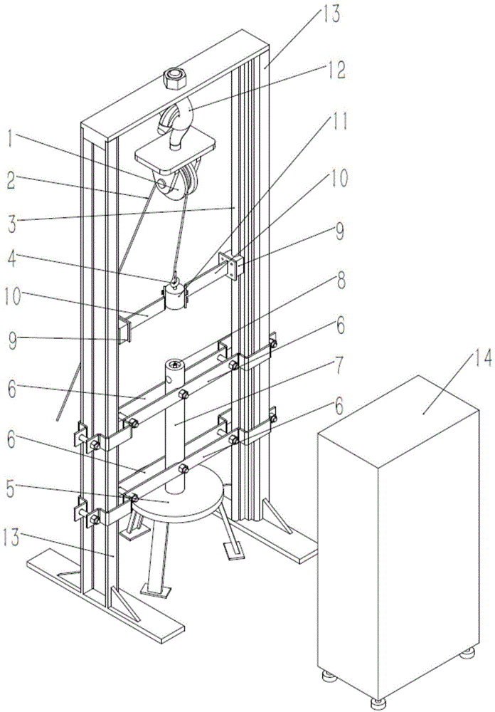
[0030] see figure 1 , Figure 2a and Figure 2b , the structural form of the small hydraulic buffer impact test device in the present embodiment is:

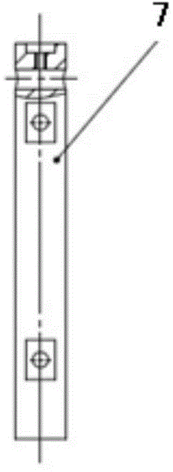
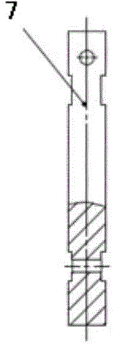
[0031] A door-shaped frame 13 composed of vertical rods 3 on both sides and cross beams connected to the tops of the vertical rods 3 on both sides is provided. In the frame 13, it is located at the lower part of the frame 13 and is fixed horizontally between the vertical rods on both sides. A splint 6 is provided, and the installation rod 7 standing upright on the support platform 5 is clamped in the splint 6. The splint 6 can be set as two upper and lower lines parallel to each other. To ensure that the hydraulic shock absorber is installed vertically and does not move axially or radially during the impact; a fixed pulley 1 is suspended on the beam by using the top ring 12, and one end of the wire rope 2 bypassing the f...


PUM


Abstract

The invention discloses a small hydraulic buffer impact test method and device, and the method comprises the following steps: first, a small hydraulic buffer is vertically fixedly arranged, a buffer rod is vertically upward, an impact load and the hydraulic buffer are arranged on a same vertical line, and the impact load is arranged on a set height above the hydraulic buffer; the impact load freely falls onto the hydraulic buffer for drop-hammer impact; a plurality of different buffer state images in the buffer process of the hydraulic buffer can be obtained by use of a high-speed camera; and finally, the number of the shot images in the buffer process can be obtained by analytic statistics by use of dichotomy, and the buffer time of the hydraulic buffer can be obtained by dividing the number of the shot images by shooting frame rate of the high-speed camera. Through measuring the buffer time of the small hydraulic buffer for further obtaining the mechanical system actuation time, the buffer property of the hydraulic buffer can be judged, the method is simple, and test results are accurate.

Description

technical field [0001] The invention relates to a test method and device for buffer performance of a hydraulic buffer, in particular to a drop-weight impact test method and device for measuring the buffer time of small hydraulic buffers such as RB0604, RJ0805 and other series. Background technique [0002] In mechanical transmission and fluid transmission, impact phenomenon often occurs. For example, the high-speed reciprocating cylinder piston rod will have a great impact on the cylinder head at the end of the stroke. When the buffer capacity inside the cylinder is insufficient, a hydraulic buffer needs to be installed outside to avoid the reduction of the service life of the cylinder. For an excellent hydraulic buffer, its buffer performance needs to be matched with the external mechanical system to minimize the impact of the mechanical system, so as to improve the smooth operation and service life of the mechanical system. For this reason, it is necessary to develop a te...

Claims


Application Information

Patent Timeline
Patent Type & Authority Applications(China)
IPC IPC(8): G01N3/303
Inventor 曾亿山冯羚青訾斌耿圣陶
Owner HEFEI UNIV OF TECH
Why Eureka
Try Eureka