Improved plate turnover machine with quick turnover function

An improved, flipping machine technology, applied in the field of sheet metal processing, can solve the problems of loud noise, falling, impact, damage to the sheet, etc., and achieve the effects of safe and reliable action, not easy to break, and reasonable and effective rotating structure

Pending Publication Date: 2021-07-02
ZHEJIANG YASHA DECORATION
View PDF1 Cites 4 Cited by
  • Summary
  • Abstract
  • Description
  • Claims
  • Application Information

AI Technical Summary

Problems solved by technology

At the beginning of the processing process, the input method of the plates is two by two, and the bright side is facing each other, so that the two bright sides do not touch the roller and protect each other, and it also has the advantage of inputting two plates at a time. , but there is also a problem in this method, that is, the visible side of the upper plate is facing downward, and the transport arm or suction cup machine must be equipped with a turning machine after moving to ensure that the bright side can be turned up during subsequent processing
[0003] The structure of the plate turning machine in the prior art mainly includes a driving motor, a motor shaft, and a support plate arranged on the motor shaft. Its working principle is that a single support plate catches a plate and then rotates, and the plate falls in the direction of rotation. On the previous support plate, the motor shaft rotates at a certain angle at last, and the plate slides down on the previous support plate and returns to the conveying roller. In this way, the basic turnover action can be completed, but the existing turnover The trigger still has the following problems: first, the board needs to be dropped once between two adjacent support boards during the flipping process, which will damage the board and cause a loud noise; second, the board has been turned over When leaving the support plate after turning over, since the way of leaving is to slide down without power, it is necessary to set the position of the roller on the side after turning over to be lower, so that the plate can slide down smoothly, and the plate will hit the roller vigorously during this process cylinder, which may damage the board
[0006] However, in the panel turning machine in this utility model patent, there is no fixed structure between the turning insert and the plate, so the plate will still fall and hit when it rotates with the turning insert, which will eventually cause the plate to be damaged. question

Method used


Image

  • Improved plate turnover machine with quick turnover function
  • Improved plate turnover machine with quick turnover function
  • Improved plate turnover machine with quick turnover function

Examples


Embodiment

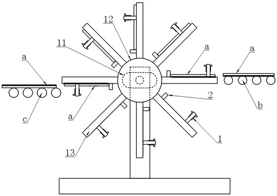
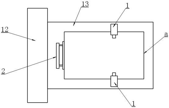
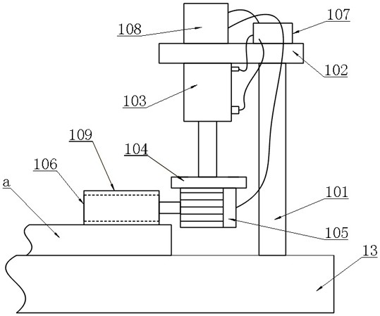
[0025] Example: as attached figure 1 , 2 , 3, 4 and attached Figure 5 As shown, an improved plate turning machine with a quick turning function includes a driving motor 11, a rotating shaft 12 arranged on the driving motor 11, and a rotating shaft 12 arranged on the rotating shaft 12 for supporting the plate The rotating plate 13 also includes a side of the rotating plate 13 that is located in the direction of rotation and is located on both sides of the plate a, and is used to push the plate a toward the direction of the rotating shaft 12 and away from the rotating shaft. The motor pressing unit 1 that pushes the plate a to be discharged in the direction of 12, and the elastic plate unit 2 that is arranged on the side of the rotating plate 13 and is used to elastically lift the plate a outward when the plate a is discharged.

[0026] In this embodiment, initially the motor pressing unit 1 is in an idle state, and the number of the rotating plates 13 is 8, when one of the r...


PUM


Abstract

The invention belongs to the technical field of plate processing, and particularly relates to an improved plate turnover machine with a rapid turnover function. According to the improved plate turnover machine, through arrangement of a rotating shaft, a rotating plate, a motor pressing unit and an elastic plate unit on a driving motor, the purposes that plates are turned over quickly and stably, and are not prone to collide and damage are achieved. The improved plate turnover machine has the advantages that a rotating structure for plate turnover is reasonable and effective, and the plate clamping type rotating turnover action is safe and reliable; the plate is not prone to damage, and a plate pushing feeding and discharging structure is simple and efficient; the mode that an elastic plate unit is pressed to store energy firstly and then assists in pushing out the plate is flexible and ingenious, and the overall plate feeding and discharging structure is rapid, labor-saving, stable and accurate; and the whole turning plate structure is stable and compact, flexible, adjustable, energy-saving and economical.

Description

technical field [0001] The invention belongs to the technical field of plate processing, and in particular relates to an improved plate turning machine with the function of quick surface turning. Background technique [0002] During the processing of the board, the side with patterns or that we can touch during use, that is, the smooth side needs to face up, the purpose is to prevent the roller from scratching the paint or lines on the smooth side. At the beginning of the processing process, the input method of the plates is two by two, and the bright side is facing each other, so that the two bright sides do not touch the roller and protect each other, and it also has the advantage of inputting two plates at a time. , but there is also a problem in this method, that is, the bright side of the upper plate is facing downward, and the transport arm or suction cup machine must be equipped with a turning machine after moving to ensure that the bright side can be turned up during...

Claims


Application Information

Patent Timeline
IPC IPC(8): B65G47/252B65G47/82
CPCB65G47/252B65G47/82
Inventor 丁欣欣丁泽成王文广钟诚朱开放方谋勇李建斌
Owner ZHEJIANG YASHA DECORATION
Why Eureka
Try Eureka