Solar energy charging system of electric automobile and control method

A technology of electric vehicles and charging systems, applied in the direction of electric vehicle charging technology, electric vehicles, battery/fuel cell control devices, etc., can solve the problems of line high voltage loss, large energy loss, large system loss, etc., to avoid vehicle driving performance impact, ease of use and management, and the effect of reducing energy loss

Active Publication Date: 2017-10-13
ZHONGTONG BUS HLDG
View PDF9 Cites 4 Cited by
  • Summary
  • Abstract
  • Description
  • Claims
  • Application Information

AI Technical Summary

Problems solved by technology

[0005] 1. Insufficient safety: The voltage generated by the solar panel on the vehicle can reach a high level when it is irradiated by strong sunlight. If the circuit connection is not well protected against high voltage, it will easily lead to high voltage loss of the line
[0006] 2. Affect driving performance: Because of actual use needs, most of the current solar charging systems adopt the mode of "charging while driving" and "charging as you use"; because of the characteristics of the battery itself, when charging the power battery It will affect the discharge of the power battery. This "charge as you use" method will cause the discharge of the vehicle's power battery to be disturbed by charging, which will affect the driving performance of the electric vehicle.
[0007] 3. Excessive system loss: Whether it is the self-storage power of the vehicle or the power provided by the solar panel, it is very precious and needs to be used with care; if the vehicle-mounted solar charging system is equipped with mechanical structures such as rotation and folding, it will cause the weight of the system itself Too large and the structure is too complex, which will not only lead to excessive energy loss of the system, but also increase the burden on the vehicle, which will have a negative impact on the mileage of the electric vehicle

Method used


Image

  • Solar energy charging system of electric automobile and control method
  • Solar energy charging system of electric automobile and control method

Examples


Embodiment Construction

[0042] Below in conjunction with accompanying drawing and embodiment, the embodiment of the present invention is described in detail as follows:

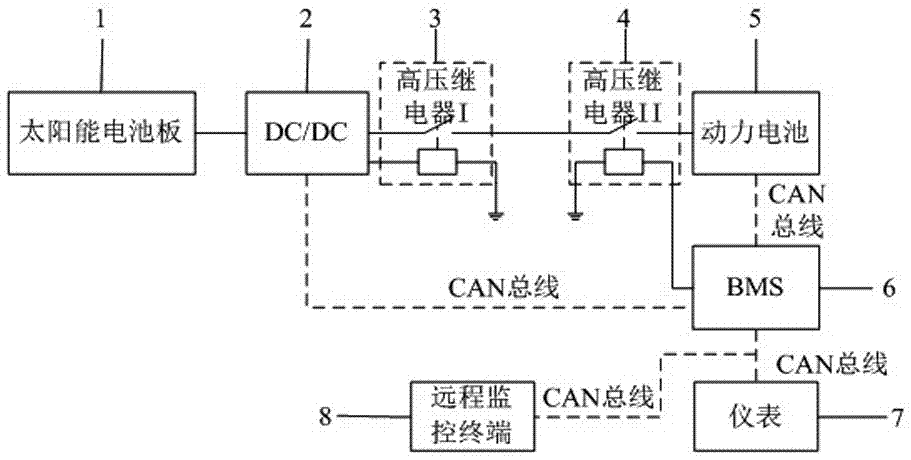
[0043] The system structure diagram is as follows figure 1 As shown, a solar charging system for electric vehicles includes:

[0044] Solar panel 1, DC / DC converter for solar charging (usually referred to as DC / DC) 2, high voltage relay I3, high voltage relay II4, power battery 5, battery manager (usually referred to as BMS) 6, instrument 7, remote Monitoring terminal 8.

[0045] The solar cell panel 1 is fixed on the roof of the electric vehicle in a horizontal manner, so as to ensure that the solar cell panel 1 can receive sunlight with the largest area and convert solar energy into electrical energy; The added resistance of the board to the electric vehicle; this setting method does not set up devices such as tilting brackets and rotating mechanisms, which not only reduces the weight of the system, but also reduces the resistan...


PUM


Abstract

The invention relates to a solar energy charging system of an electric automobile and a control method. The solar energy charging system comprises a solar energy battery panel, a solar energy charging DC / DC (direct current-direct current) converter (usually referred to as DC / DC for shot), a high-voltage relay I, a high-voltage relay II, a power batter, a battery management system (usually referred to as BMS for short), an instrument and a remote monitoring terminal. The solar energy charging system is not only capable of charging the electric automobile, but also capable of guaranteeing driving performance of the electric automobile since operation of the solar energy charging system is more convenient and fast and safer in operation. According to the control method, remaining capacity of the power battery is monitored by the battery management system (BMS), charging can only be started when the remaining capacity is less than 50%, a charging manner of 'random charging during use' is avoided from influencing the driving performance of the electric automobile to the greatest extent, and time for a normal driving state of the electric automobile is prolonged.

Description

technical field [0001] The invention relates to the field of electric vehicle parts and control systems, in particular to an electric vehicle solar charging system and a control method. Background technique [0002] Electric vehicles are becoming more and more popular in the market, and the mileage and charging issues of electric vehicles are getting more and more attention. At present, electric vehicles can only be charged at special charging stations; however, the number of charging stations is very small, especially in small and medium-sized cities and along highways, which greatly restricts the charging of electric vehicles. It affects the normal operation of electric vehicles, and also restricts the speed of popularization of electric vehicles in the market. [0003] In order to cope with this dilemma, those skilled in the art have proposed many solutions, such as using hybrid power for vehicles, distributing charging stations more scientifically, improving charging co...

Claims


Application Information

Patent Timeline
Patent Type & Authority Applications(China)
IPC IPC(8): B60L8/00B60L11/18
CPCB60L8/003B60L53/20B60L58/10Y04S30/12Y02T10/7072Y02T10/72Y02T90/167Y02T10/70Y02T90/14
Inventor 翁福建赵红光李阳李晓辉周传东付志强高顺来田鹏武纪强于东超黄志宇
Owner ZHONGTONG BUS HLDG
Why Eureka
Try Eureka