Clamp mechanism for steel plate conveying trolley

A technology for conveying trolleys and clamps, which is applied to the details of milling machine equipment, metal processing, and metal processing equipment. It can solve problems such as complex mechanisms, clamps that cannot be lifted up and down, and high manufacturing costs. It achieves safe and reliable actions, simple structure, and manufacturing low cost effect

Active Publication Date: 2010-10-13
WUXI HUALIAN SCI & TECH GROUP
View PDF5 Cites 5 Cited by
  • Summary
  • Abstract
  • Description
  • Claims
  • Application Information

AI Technical Summary

Problems solved by technology

[0002] In the prior art, the tongs may not be able to be lifted, and the alternate use of tongs conveying and roller conveying cannot be realized, or the lifting of the tongs is often achieved by means of elevators, etc.
These methods have poor reliability, complex mechanism and high manufacturing cost.

Method used


Image

  • Clamp mechanism for steel plate conveying trolley
  • Clamp mechanism for steel plate conveying trolley
  • Clamp mechanism for steel plate conveying trolley

Examples


Embodiment Construction

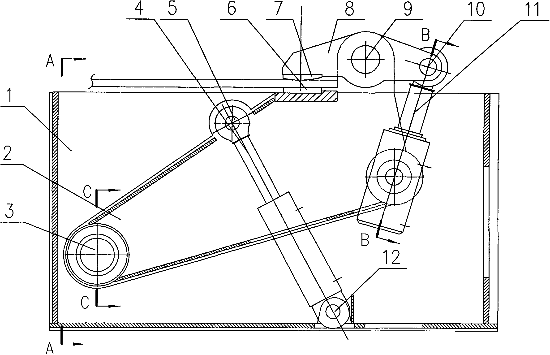
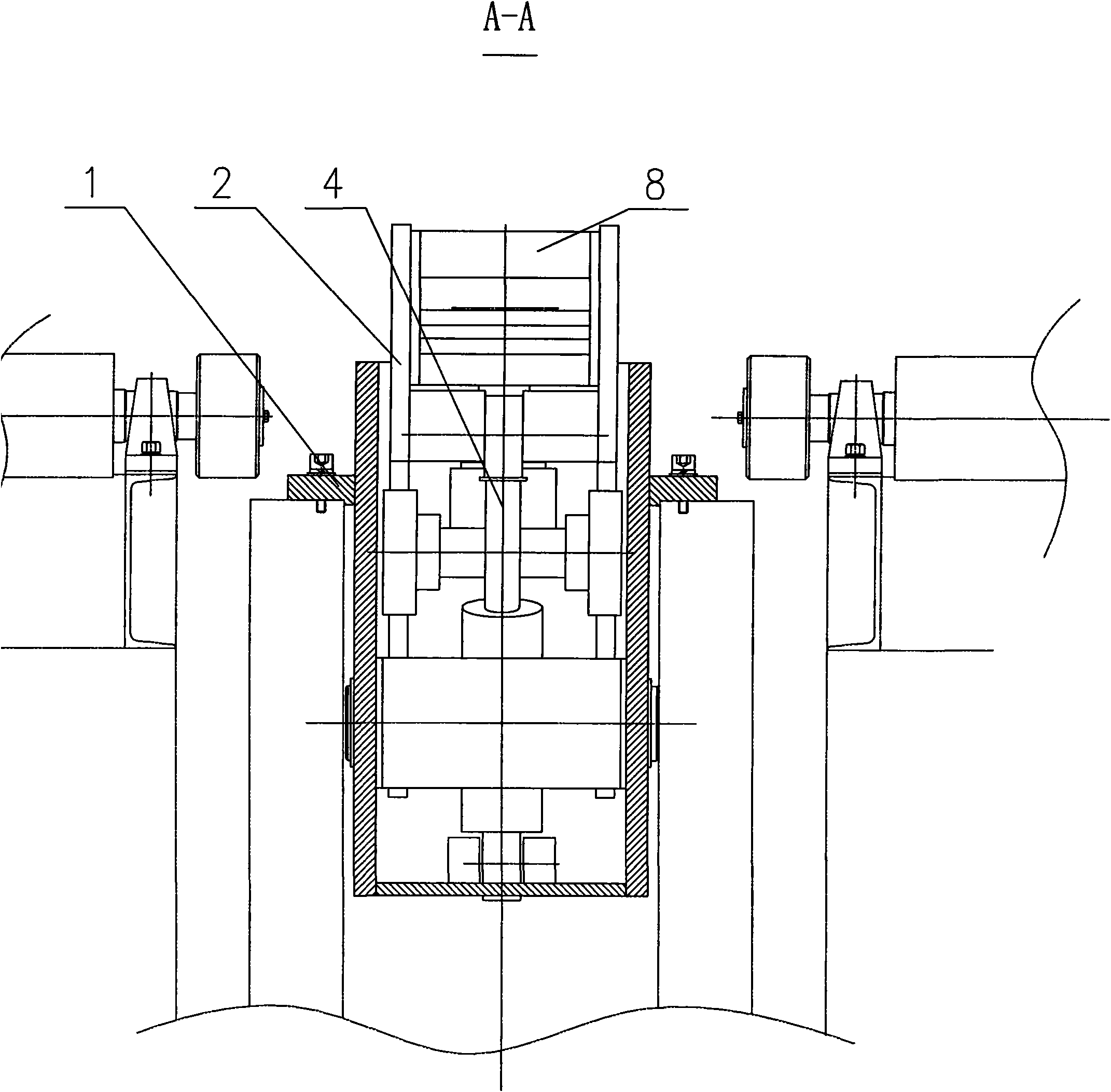
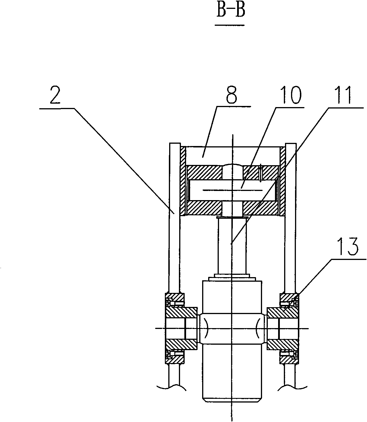
[0012] Below the present invention will be further described in conjunction with the embodiment in the accompanying drawing:

[0013] like Figure 1 ~ Figure 4 As shown, the present invention mainly includes a frame body 1, a swing arm 2, a first pin shaft 3, a swing hydraulic cylinder 4, a second pin shaft 5, a lower jaw 6, an upper jaw 7, a jaw body 8, and a third pin shaft 9. The fourth pin shaft 10, the clamping hydraulic cylinder 11, the fifth pin shaft 12, the oil cylinder mounting seat 13, the copper sleeve 14, and the pressure plate 15. The swing arm 2 is connected to the frame body 1 by the first pin shaft 3, the pressure plate 15 is fixed on both ends of the first pin shaft 3 by bolts, and the copper sleeve 14 is installed in the shaft hole of the swing arm 2. One end of the swing hydraulic cylinder 4 is connected to the swing arm 2 by the second pin shaft 5, the other end is connected to the frame body 1 by the fifth pin shaft 12, and the middle part of the clamp b...


PUM


Abstract

The invention relates to a clamp mechanism for a steel plate conveying trolley in a steel plate edge-milling device. A swing arm is connected with a frame body by adopting a first pin shaft; a pressure plate is fixedly mounted at two ends of the fin shaft by using bolts; a copper sleeve is mounted in a shaft hole of the swing arm; one end of a swing hydraulic cylinder is connected to the swing arm by using a second pin shaft, and the other end of the swing hydraulic cylinder is connected with the frame body by using a fifth pin shaft; the middle part of a clamp body is connected with the swing arm by using a third pin shaft; a pin shaft for clamping the middle part of the hydraulic cylinder is mounted on the swing arm by using an oil cylinder mounting seat, and the other end of the hydraulic cylinder is connected with the end part of the clamp by using a forth pin shaft; an upper clamp opening is connected with the clamp body by using bolts, and a lower clamp opening is connected with the swing arm by using bolts. The invention has simple, compact and reasonable structure, safe and reliable action and low manufacture cost, and is suitable for clamping of steel plates in the steel plate edge-milling device.

Description

technical field [0001] The invention relates to a steel plate conveying trolley clamp mechanism in steel plate edge milling equipment. This mechanism is installed on the conveying vehicle and placed in the middle of the conveying roller table. Specifically, it adopts a hydraulic drive to loosen and clamp the clamps for pinching steel plates, and can swing up and down to meet the alternate use of clamp conveying and roller conveying, which belongs to the technical field of mechanical equipment. Background technique [0002] In the prior art, the tongs may not be able to be lifted, and the alternate use of the tongs conveying and the roller conveying cannot be realized, or the tongs are often lifted and lowered by means of elevators and the like. These methods have poor reliability, complex mechanism and high manufacturing cost. Contents of the invention [0003] The object of the present invention is to overcome the above disadvantages, thereby providing a clamp mechanism...

Claims


Application Information

Patent Timeline
Patent Type & Authority Applications(China)
IPC IPC(8): B23C9/00B23Q7/00
Inventor 桂重孙志明周军记龚国华曹益民杨念记任乐
Owner WUXI HUALIAN SCI & TECH GROUP
Why Eureka
Try Eureka