Suction opening structure of compressor

A suction port and compressor technology, which is applied in the field of compressors, can solve the problems of ceramic tube length not being too long, high installation precision of liquid storage tank, and reduced heat insulation effect, so as to reduce adverse effects, easy to ensure assembly tolerance, The effect of increasing the insulating area

Inactive Publication Date: 2012-12-19
LG ELECTRONICS (TIANJIN) APPLIANCES CO LTD
View PDF6 Cites 12 Cited by
  • Summary
  • Abstract
  • Description
  • Claims
  • Application Information

AI Technical Summary

Problems solved by technology

[0008] However, the direct contact between the exhaust pipe of the liquid storage tank and the ceramic is only fixed by a single degree of freedom in the horizontal direction, which is easily affected by the vibration of the compressor and causes the ceramic tube to break. In addition, due to the limitation of the size of the shell and the liquid storage tank, the The length of the pipe should not be too long, as this will reduce the insulation effect
Due to the direct contact method of fixing, the dimensional accuracy of ceramic processing and the installation accuracy of the liquid storage tank will be very high, which is not conducive to assembly

Method used


Image

  • Suction opening structure of compressor
  • Suction opening structure of compressor
  • Suction opening structure of compressor

Examples


Embodiment Construction

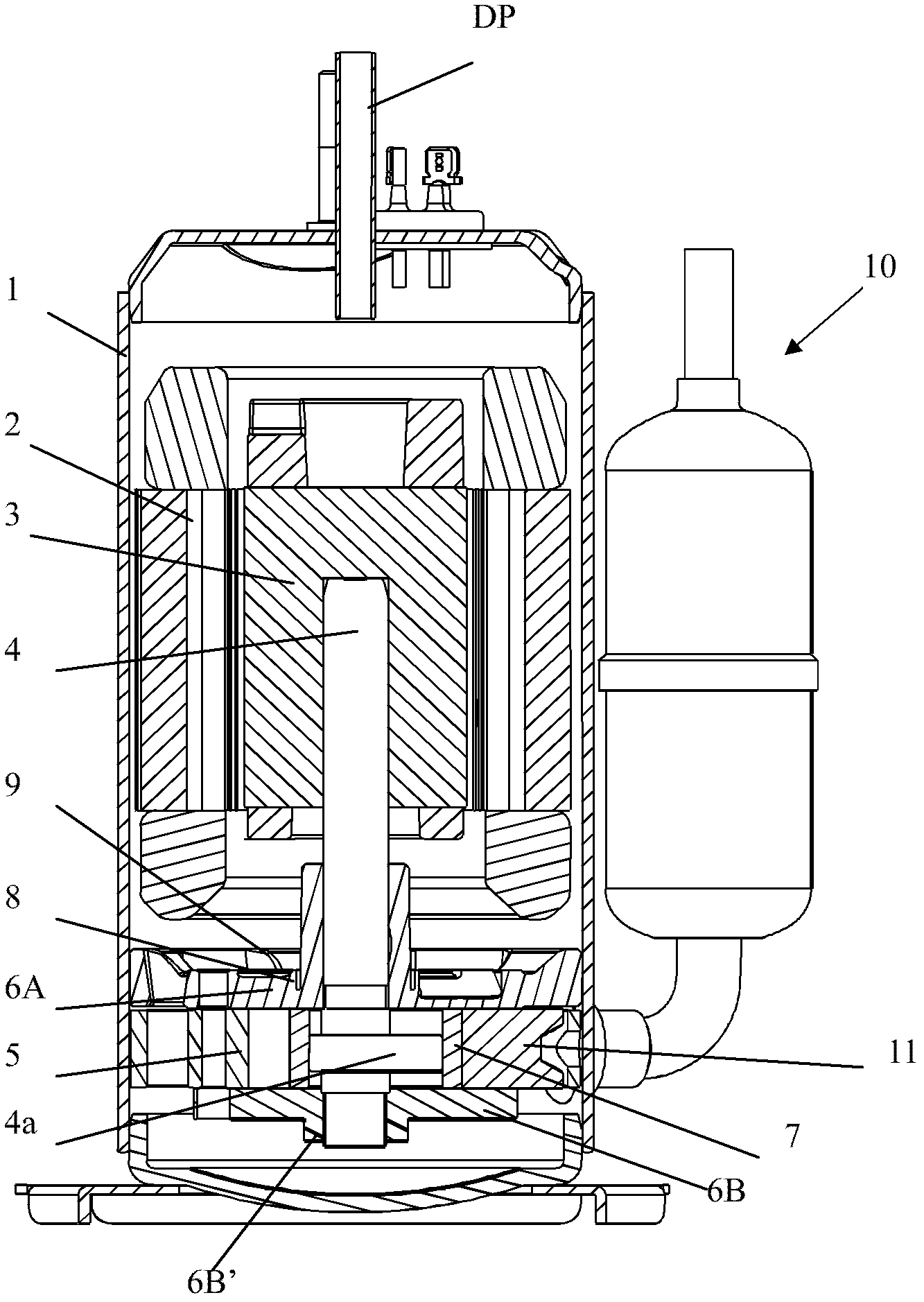
[0020] The structure of the rotary compressor of the present invention will be described in detail below with reference to the accompanying drawings.

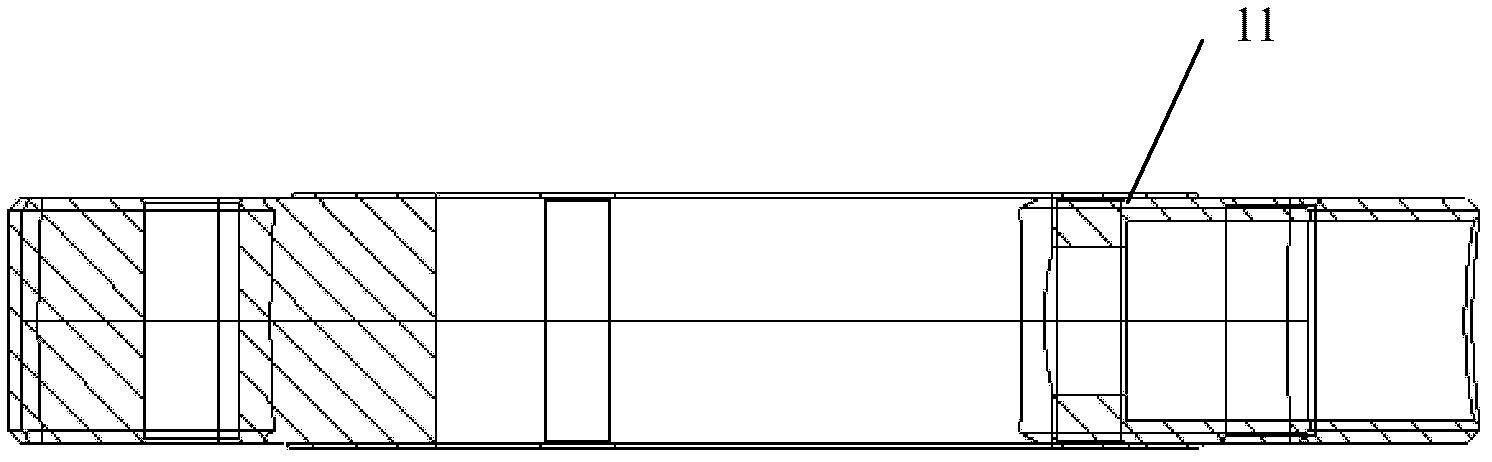
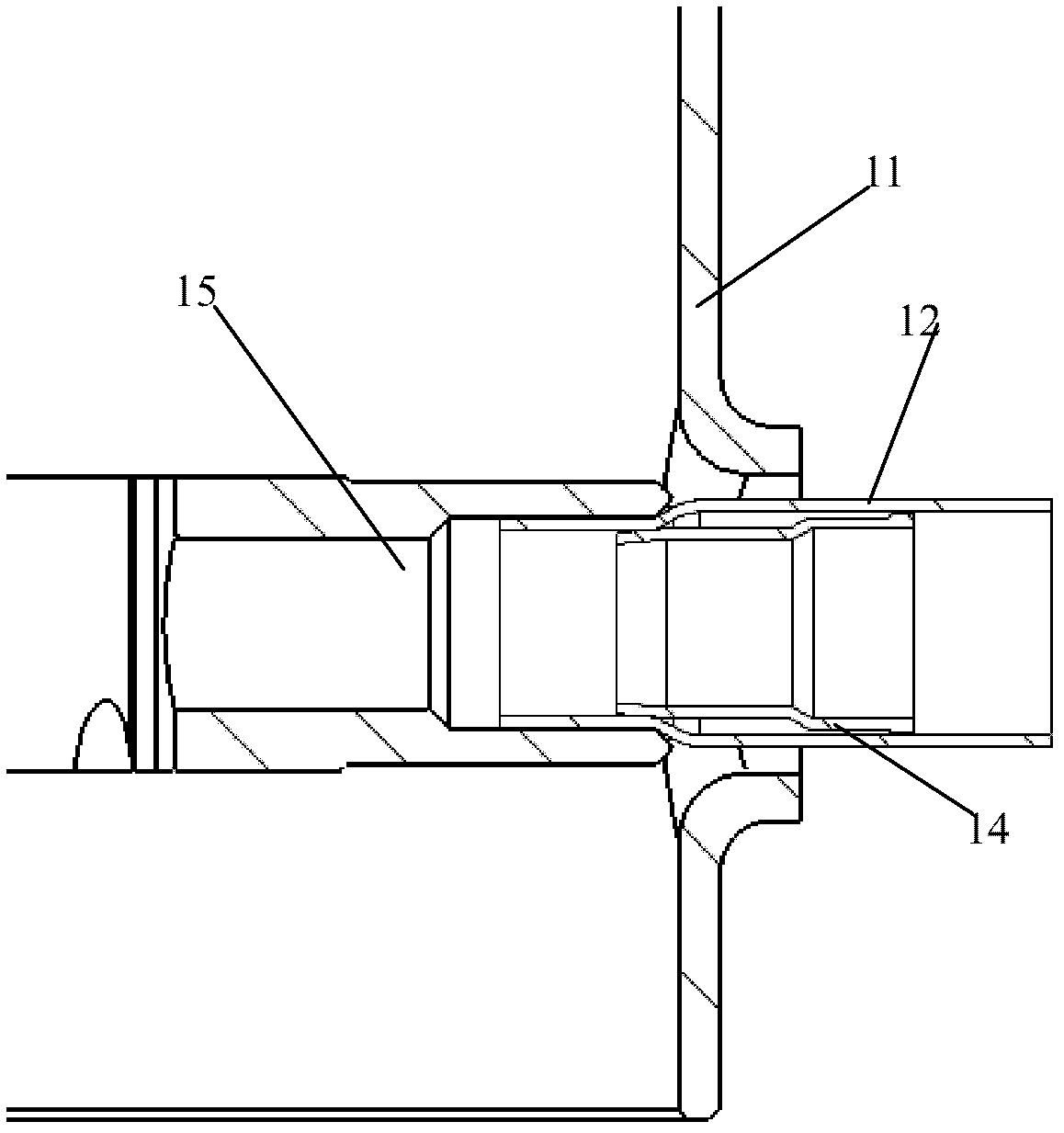
[0021] The structure of the compressor of the present invention is basically the same as that of the prior art, and its electric structural part includes: a stator, a rotor and a crankshaft. The stator and the rotor are arranged inside the casing, the center of the rotor is press-fitted and installed on the crankshaft, and the lower part of the crankshaft is provided with a compression structure for sucking and compressing the refrigerant gas. The compression structure part includes: a circular cylinder fixedly arranged on the inner peripheral surface of the casing; an upper bearing and a lower bearing which are closely fixed on the upper and lower sides of the cylinder while the crankshaft passes through and is supported; On the eccentric part, the roller ring rotates eccentrically in the cylinder under the action of the crank...


PUM


Abstract

The invention discloses a suction opening structure of a compressor. The suction opening structure comprises a suction pipe which is fixedly connected with a suction port of a cylinder, a heat-insulation ceramic tube which is fixedly arranged inside the suction pipe, and a liquid storage tank's exhaust pipe which is fixedly connected with the suction pipe. A taper surface is formed on the external end portion of the heat-insulation ceramic tube. A bell mouth which fits with the taper surface is formed on the end portion of the liquid storage tank's exhaust pipe. The heat-insulation ceramic tube fits with the liquid storage tank's exhaust pipe through the taper surface. An assembly operator can conveniently perform total freedom degree of contact between the liquid storage tank's exhaust pipe and the end portion of the heat-insulation ceramic tube. Fitting allowance is easy to guarantee. In addition, axial freedom degree of the heat-insulation ceramic tube is restricted, and adverse influence of shock during the operation process of the compressor on the heat insulation ceramic is relatively reduced. Simultaneously, it is ensured that dimensions of the housing and subsidiary parts are not changed. In this case, as the end portion of the heat-insulation ceramic tube extends into the inside of an exhaust pipe, the length of the heat-insulation ceramic tube is relatively increased, heat insulation area is increased, and inhalation efficiency is more effectively raised.

Description

technical field [0001] The invention relates to the field of compressors, in particular to a suction port structure of a rotary compressor. Background technique [0002] Rotary compressors suitable for air conditioners, etc. are usually eccentrically combined with the rotary piston of the compression structure on the crankshaft combined with the electric structure. The rotary piston rotates in the compression space of the circular cylinder to suck in, compress and discharge refrigeration. agent. [0003] figure 1 For the longitudinal section of the existing rotary compressor, such as figure 1 As shown, its electric structural part includes: stator 2, rotor 3 and crankshaft 4. The stator 2 and the rotor 3 are arranged inside the casing 1, and the center of the rotor 3 is pressed into the crankshaft 4, and the lower part of the crankshaft 4 is provided with a compression structure for sucking and compressing the refrigerant gas. The compression structure part includes: a c...

Claims


Application Information

Patent Timeline
Patent Type & Authority Applications(China)
IPC IPC(8): F04C29/12
Inventor 李小川许崇文
Owner LG ELECTRONICS (TIANJIN) APPLIANCES CO LTD
Why Eureka
Try Eureka