Eureka AIR delivers breakthrough ideas for toughest innovation challenges, trusted by R&D personnel around the world.

Chain-type pin wheel transmission device

A transmission device and pin wheel technology, which is applied in the direction of transmission device, friction transmission device, belt/chain/gear, etc. question

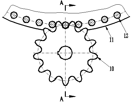
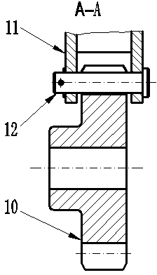
Inactive Publication Date: 2012-12-19
赵庆国
View PDF7 Cites 2 Cited by
  • Summary
  • Abstract
  • Description
  • Claims
  • Application Information

AI Technical Summary

Problems solved by technology

[0007] Although the existing pin-tooth transmission has its advantages, the fixed mode of the pin wheel rotating in a circular path limits the scope of use of the pin-tooth transmission, especially in large-scale applications, because it can only run circular paths. The layout of the site is not conducive to the effective use of the site and the expansion of the transportation function
[0008] Although the chain transmission in the prior art can run a limited non-circular path, there are defects such as the range of the sprocket wrap angle should not be too small, heavy load and continuous long-term operation, and large transmission impact;

Method used


Image

  • Chain-type pin wheel transmission device
  • Chain-type pin wheel transmission device
  • Chain-type pin wheel transmission device

Examples


Embodiment 1

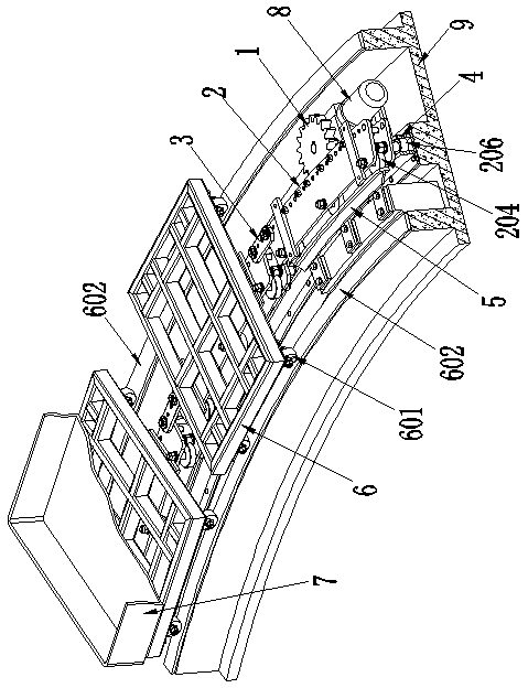
[0133] A chain pin wheel drive (see Figure 3 ~ Figure 5 ), which includes a chain pin wheel and a gear 1, and a guide device 4; the chain pin wheel is composed of 37 pin wheel units; each pin wheel unit is sequentially connected in series, and the specific connection method is hinged; each pin wheel hinged in series The unit is arranged along the gourd-shaped running path E provided by the guide device 4 to form a chain pin wheel (see Figure 10 , Figure 11 ).

[0134] The chain pin wheel is also specifically provided with a transmission pin 201 fixed on the pin wheel unit for meshing with the gear 1, and the distance between every two adjacent transmission pins 201 in the chain pin wheel is equal and together constitutes The gear teeth of the chain pin wheel; the gear 1 forms a multi-section movable pin tooth transmission structure through the transmission pin 201 and the chain pin wheel.

[0135] Present embodiment also comprises following preferred content:

[0136] I...

Embodiment 2

[0184] This embodiment is mostly the same as Embodiment 1, the difference is:

[0185] 1. A chain type pin wheel transmission device, the chain type pin wheel is composed of 10 pin wheel units; the series hinged pin wheel units are arranged along the closed elliptical running path E provided by the guide device 4 to form a chain type pin wheel (see Figure 9 );

[0186] 2. The main rack 2 and the short rack 3 of the pin wheel unit meet the following requirements:

[0187] The length ratio of the main tooth span M to the short tooth span N, that is, M / N, is 6; the two adjacent main racks 2 can swing relative to each other, and the range of the relative swing angle, that is, the swing angle β, is +27.6° ~+48.6°; the distribution line D of the transmission pin of the main rack 2, the distribution line U of the guide wheel and the distribution line H of the balance wheel are concentric arcs; the number of transmission pins 201 on the main rack 2 is 18, and the short rack 3. The ...

Embodiment 3

[0214] This embodiment is mostly the same as Embodiment 1, the difference is:

[0215] 1. A chain-type pin-wheel transmission device, the chain-type pin-wheel is composed of 200 pin-wheel units; the pin-wheel units hinged in series are arranged along the rectangular closed running path E provided by the guide device 4 to form a chain type pin wheel (see Figure 12 ).

[0216] 2. Selection of the driving section F in the chain pin wheel drive:

[0217] The running path E of the chain-type pin wheel transmission device is composed of four straight lines and four circular arcs sequentially combined in series; the straight line and the circular arc in the path are connected tangentially to form a continuous running path E. This embodiment is based on The characteristics of the running path E, a driving section F is set in the middle of the four straight lines in the running path E, and the transmission type of the pin-rack meshing is adopted.

[0218] 3. The main rack 2 and the...


PUM

PropertyMeasurementUnit
Diameteraaaaaaaaaa
Diameter sizeaaaaaaaaaa
Diameteraaaaaaaaaa

Abstract

The invention relates to a chain-type pin wheel transmission device which comprises a chain-type pin wheel, a gear (1) and a guide device (4). The chain-type pin wheel is formed by at least 10 pin wheel units; the pin wheel units are sequentially connected in series; the pin wheel units which are connected in series and hinged are arranged along the guide device (4) to form the chain-type pin wheel; drive pins (201) which are fixed on the pin wheel units and are used for being meshed with the gear (1) are also particularly arranged in the chain-type pin wheel; the distances between each two drive pins (201) in the chai-type pin wheel are equal; and a multi-section movement pin tooth transmission structure is formed between the gear (1) and the chain-type pin wheel by the drive pins (201). According to the invention, a fixed mode that the pin wheel needs to move according to a round path is broken through, so that in the pin tooth driving process, the pin wheel can operate according to an oval path or a sealed or unsealed path formed by sequentially and smoothly connecting any one of combinations of curves and straight lines and a combination of curves. The chain-type pin wheel transmission device has foreseeable huge economic value and social value.

Description

technical field [0001] The invention relates to the technical field of transmission device structure design, and in particular provides a chain type pin wheel transmission device. Background technique [0002] So far, in pin-tooth transmissions at home and abroad, the pin wheels that cooperate with the gears have fixed structural shapes. Its shape is circular in the literature; driven by the gear, the pin wheel rotates in a fixed circular path. [0003] According to the editor-in-chief of Cheng Daxian, the third volume 14-555 of the fifth edition of the "Mechanical Design Manual" published by the Chemical Industry Press, the pin gear transmission belongs to a special form of gear transmission in the prior art, and the large gear with round pin teeth is called a pin wheel (circular one-piece rigid structural form), while another pinion with a general gear tooth profile is usually called a gear (cf. figure 1 , figure 2 ). [0004] Pin-tooth transmission has three transmis...

Claims


Application Information

Patent Timeline
IPC IPC(8): F16H7/06F16H19/00
Inventor 赵庆国
Owner 赵庆国
Why Eureka
Eureka Blog
Learn More