A switchable regenerative high-efficiency heat exchanger

A technology of heat exchanger and heat storage type, which is applied in the field of heat storage heat exchange devices, to achieve the effect of overcoming large changes in the furnace, rapid operation, and improving combustion efficiency

Active Publication Date: 2015-08-12
CENT SOUTH UNIV
View PDF4 Cites 0 Cited by
  • Summary
  • Abstract
  • Description
  • Claims
  • Application Information

AI Technical Summary

Problems solved by technology

However, due to the fact that there is no heat exchange device that fully meets the requirements, none of them can be well realized.

Method used


Image

  • A switchable regenerative high-efficiency heat exchanger
  • A switchable regenerative high-efficiency heat exchanger
  • A switchable regenerative high-efficiency heat exchanger

Examples


Embodiment Construction

[0031] The present invention will be further described below in conjunction with accompanying drawing.

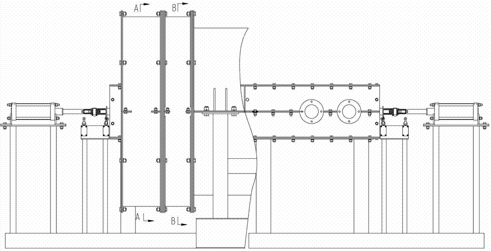
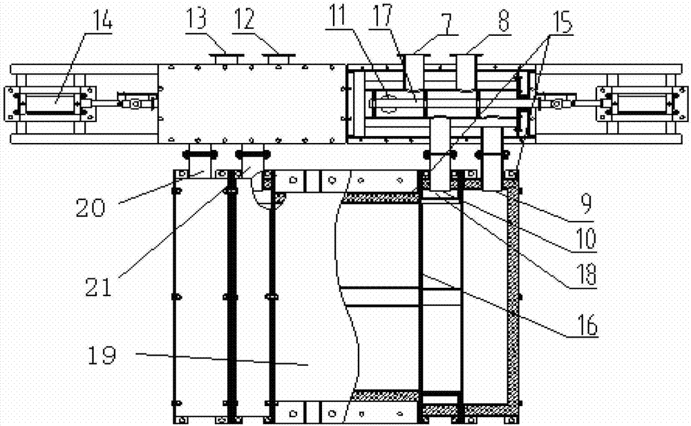
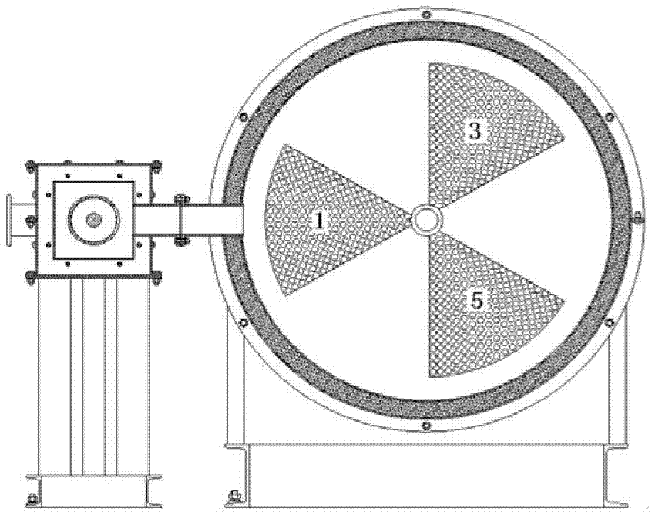
[0032] see figure 1 , figure 2 , image 3 , Figure 4 , Figure 8 and Figure 9 , the inner wall of the axial housing 19 is provided with a thermal insulation layer 15, and the interior of the axial housing 19 is divided into six equal axial cavities by partitions: the first cavity 1, the second cavity 2, the third cavity The cavity 3, the fourth cavity 4, the fifth cavity 5 and the sixth cavity 6, and the axial casing 19 are all filled with regenerators, and the regenerators are divided into ceramic balls according to different flue gas qualities: ceramic balls 28 and ceramic honeycomb29. Both ends of the axial cavity are provided with perforated baffles 16 for fixing the heat storage body, and the perforated baffles 16 are fixed together with the axial housing 19 by bolts for easy replacement. The axial housing 19 is provided with a first air pipe 10 and a second ...


PUM


Abstract

The invention discloses a switchover heat accumulating type efficient heat exchanger. The inside part of a cylindrical shell (19) is divided into six equal axial cavities which are internally filled with heat accumulators by using partition boards; a first air pipe (10) and a second air pipe (21), which are communicated with the both ends of three axial cavities, are respectively arranged on the cylindrical shell (19); a third air pipe (9) and a fourth air pipe (20), which are communicated with the both ends of the other three axial cavities, are respectively arranged on the cylindrical shell (19); the first air pipe (10) and the third air pipe (9) are respectively alternatively communicated with a first air inlet pipe (8) and a first air discharging pipe (7) through a first gas reversing device; and the second air pipe (21) and the fourth air pipe (20) are respectively alternatively communicated with a second air inlet pipe (13) and a second air discharging pipe (12) through a second air reversing device. According to the switchover heat accumulating type efficient heat exchanger provided by the invention, a heat accumulation chamber is still, and the continuous hot air supply and the cooling smoke discharge of the nozzle can be realized.

Description

technical field [0001] The invention relates to a regenerative heat exchange device. Background technique [0002] The tension and shortage of energy in our country is a foregone conclusion, which has seriously affected the economic development. In the heat treatment of industrial plants, large quantities of exhaust gases with a high heat content are frequently produced, which offers an economic advantage for the recovery of the exhaust gases at the very times when energy consumption usually occurs. At present, the energy utilization rate of industrial furnaces in my country is generally low. Now there are some forging heating furnaces. Due to the characteristics of process operation, the exhaust gas temperature of most forging heating furnaces is higher than 1000 °C. [1] , because there is no high-efficiency waste heat recovery device suitable for long-term use, the heat loss of the exhaust gas is very large, so that the thermal efficiency of the furnace is only 5% to 10%,...

Claims


Application Information

Patent Timeline
Patent Type & Authority Patents(China)
IPC IPC(8): F23L15/00F27D17/00
CPCY02E20/34
Inventor 闫红杰周孑民母福生栗慧孟楠杨万青
Owner CENT SOUTH UNIV
Why Eureka
Try Eureka