Method and device for detecting rotation state of rotation part
A technology for detecting rotation and rotation state, applied in the field of electronics, can solve the problems of waste of processor resources and slow response, and achieve the effect of small delay and saving processor resources
- Summary
- Abstract
- Description
- Claims
- Application Information
AI Technical Summary
Problems solved by technology
Method used
Image

Examples
Embodiment Construction
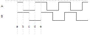
[0026] The rotating parts generally generate a square wave signal that can represent the rotation state of the rotating parts through a mechanical encoder or a photoelectric encoder, such as figure 1 shown. Signal A and Signal B have the same period, and Signal B lags Signal A by 90 degrees in phase. In the present invention, the square wave signal can be generated by the mechanical encoder or the photoelectric encoder, and can also be generated by other waveform generating circuits. A combination of mechanical structures, optoelectronic devices, and electronic circuits with high-degree square wave signals. Other phase difference values may also be used for the A signal and the B signal.
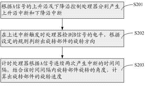
[0027] Please refer to figure 2 , a specific embodiment of the method for detecting the rotational state of the rotating part of the present invention includes the following steps:
[0028] S201. Control the processor to generate a rising edge interrupt and a falling edge interrupt re...
PUM
 Abstract
Description
Claims
Application Information
 - Generate Ideas
- Intellectual Property
- Life Sciences
- Materials
- Tech Scout
- Unparalleled Data Quality
- Higher Quality Content
- 60% Fewer Hallucinations
Browse by: Latest US Patents, China's latest patents, Technical Efficacy Thesaurus, Application Domain, Technology Topic, Popular Technical Reports.
© 2025 PatSnap. All rights reserved.Legal|Privacy policy|Modern Slavery Act Transparency Statement|Sitemap|About US| Contact US: help@patsnap.com