Heat radiating fan and power supply device

A heat dissipation fan and power supply device technology, which is applied in the direction of measuring devices, data processing power supplies, and electrical digital data processing, etc., can solve problems such as increasing air flow resistance, reducing air flow, and large circuit board changes, so as to improve work efficiency. The effect of improving quality, improving service life and saving internal space

Inactive Publication Date: 2012-12-19
DELTA ELECTRONICS POWER (DONGGUAN) CO LTD
View PDF5 Cites 1 Cited by
  • Summary
  • Abstract
  • Description
  • Claims
  • Application Information

AI Technical Summary

Problems solved by technology

[0007]1. Redesign the control circuit board 93 inside the power supply unit 9, and directly install or insert the thermal element 92 to another control circuit near the cooling fan 94 on the board 96, but this method will make the circuits of the circuit boards 93, 96 change greatly, so it is not a cost-effective way
[0008]2. Fix the thermal element 92 on a part close to the new air inlet with screws, nuts, fixing seats and other tools, and then use wiring The signal is transmitted back to the original control circuit board 93, but the main defect of this method is that the heat-sensitive element 92, the fixing tool and its wiring are very likely to block the airflow channel, increase the airflow resistance, reduce the airflow rate, and affect the overall heat radiation

Method used


Image

  • Heat radiating fan and power supply device
  • Heat radiating fan and power supply device
  • Heat radiating fan and power supply device

Examples


Embodiment Construction

[0047] The following descriptions of the various embodiments refer to the accompanying drawings to illustrate specific embodiments in which the present invention can be practiced. The directional terms mentioned in the present invention, such as "up", "down", "front", "back", "left", "right", "inside", "outside", "side", etc., are for reference only The orientation of the attached schema. Therefore, the directional terms used are used to illustrate and understand the present invention, but not to limit the present invention.

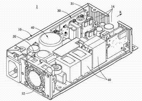
[0048] Please refer to figure 2 As shown, it shows the internal structure of one embodiment of the power supply device 1 of the present invention and the wind flow direction B inside the power supply device 1 . The power supply device 1 of the present invention includes an outer casing 10 , a cooling fan 20 installed in the outer casing 10 , a control circuit board 30 installed in the outer casing 10 , and a plurality of electronic components 40 . Th...


PUM


Abstract

The invention discloses a heat radiating fan and a power supply device. The heat radiating fan comprises a frame body, a fan circuit board, a fan motor, a plurality of motors and a thermosensitive element, wherein the frame body is provided with an air inlet side and an air outlet side and a substrate is formed at the center of the air outlet side. The fan circuit board is arranged on the substrate of the frame body; the fan motor is arranged on the substrate of the frame body and is electrically connected to the fan circuit board; the fan blades are arranged on the fan motor; and the thermosensitive element is arranged on the fan circuit board or frame body, so that the heat radiating fan disclosed by the invention has a function of sensing the temperature. The heat radiating fan is applied to the power supply device, so that an internal space of the power supply device can be saved; and reliable temperature information can be provided for the power supply device so as to improve the work quality of the power supply device.

Description

technical field [0001] The invention relates to a heat dissipation fan and a power supply device, in particular to a heat dissipation fan provided with a heat sensitive element and a power supply device using the heat dissipation fan. Background technique [0002] At present, cooling fans have become a necessary device for various electronic equipment and electronic systems. For example, cooling fans need to be provided in power supply units of computers and servers, computer chassis and some electronic products to help these devices dissipate heat and cool down. In addition, a thermosensitive element (NTC) usually needs to be installed in the power supply device to sense the temperature, so as to achieve the purpose of precise control of the power supply device. [0003] Please refer to figure 1 As shown, it shows the internal structure of the traditional power supply device 9 and the wind flow direction A inside the power supply device 9. The traditional power supply devi...

Claims


Application Information

Patent Timeline
Patent Type & Authority Applications(China)
IPC IPC(8): G06F1/20G06F1/26
CPCG06F1/20
Inventor 陈智飞
Owner DELTA ELECTRONICS POWER (DONGGUAN) CO LTD
Why Eureka
Try Eureka