
Rotation constellation diagram based coding and decoding method for spatial multiplex multi-aerial system

A technology of multi-antenna system and codec method, applied in the field of mobile communication multiple-input multiple-output (MIMO) antenna

Inactive Publication Date: 2012-12-19
SOUTH CHINA UNIV OF TECH
View PDF5 Cites 26 Cited by
  • Summary
  • Abstract
  • Description
  • Claims
  • Application Information

AI Technical Summary

Problems solved by technology

However, no one has introduced the method of rotating the constellation diagram into the signal modulation of the space division multiplexing multi-antenna system in which the transmission signals of each channel are independent of each other.

Method used


Image

  • Rotation constellation diagram based coding and decoding method for spatial multiplex multi-aerial system
  • Rotation constellation diagram based coding and decoding method for spatial multiplex multi-aerial system
  • Rotation constellation diagram based coding and decoding method for spatial multiplex multi-aerial system

Examples


Embodiment Construction

[0044] The present invention will be further described below with reference to the accompanying drawings and in combination with specific embodiments and simulation measurement results.

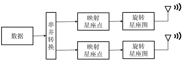
[0045] figure 1 It is a schematic diagram of a space division multiplexing multi-antenna system with 2 transmitting antennas using a rotating constellation encoding method. As can be seen from the figure, the signal is divided into two paths after serial-to-parallel conversion, and the expression is as follows:

[0046] X = X 1 · · · X k = X 1 1 · ...


PUM


Abstract

The invention discloses a rotation constellation diagram based coding and decoding method for a spatial multiplex multi-aerial system. According to the method, the rotation constellation diagram based coding and decoding method and the spatial multiplex multi-aerial system are combined, a transmission signal is subjected to serial and parallel conversion at a transmitting end and a mapped onto a modulation constellation diagram, all constellation points rotate by using origin points as circle centers at set angles and reversely rotate at the same set angles after signs are detected at a receiving end, a signal sequence is modulated through the constellation diagram and is subjected to parallel and serial conversion, and the signal is output. By the method, the problem of error rate increase caused by constellation point overlap in a related channel is solved, and the error rate of the spatial multiplex multi-aerial system in the related channel is reduced better on the premise of not increasing system bandwidth resources and unnecessarily reducing transmission rate. Compared with the traditional spatial multiplex multi-aerial system, only a rotation factor is multiplied at the transmitting end and the receiving end, and the coding method is low in hardware cost and excellent in error code performance.

Description

technical field [0001] The invention belongs to the technical field of mobile communication multiple-input multiple-output (MIMO) antennas, in particular to a coding and decoding method based on a rotating constellation diagram for a space-division multiplexing multiple-antenna system in related channels. technical background [0002] Multi-antenna technology refers to a comprehensive technology that uses multiple antennas at the transmitting end or receiving end of wireless communication and combines advanced signal processing technology at the same time. If multiple antennas are used at the sending end and the receiving end at the same time, it is possible to establish multiple parallel information transmission channels on the shared wireless channel. This is MIMO (Multiple Input Multiple Output) technology, or space division multiplexing ( Spatial Multiplex) technology. Currently the most popular signal transmission architecture for MIMO systems is the BLAST (Bell Labs L...

Claims


Application Information

Patent Timeline
IPC IPC(8): H04L1/00H04L1/06
Inventor 柯峰张钺冯穗力陈晓彬杨嘉兴李帅
Owner SOUTH CHINA UNIV OF TECH
Learn More