Universal cutter head differential mechanism and machine tool

A universal milling head and differential technology, which is used in metal processing machinery parts, metal processing equipment, precision positioning equipment, etc., can solve problems such as affecting processing production, inability to adjust, and inability to accurately position, and achieve the effect of improving indexing performance.

Inactive Publication Date: 2015-01-14
SANY GRP
View PDF5 Cites 0 Cited by
  • Summary
  • Abstract
  • Description
  • Claims
  • Application Information

AI Technical Summary

Problems solved by technology

At present, domestic accessory head manufacturers have done little research on universal heads. The indexing accuracy of the successfully developed universal heads is generally 1°, 2.5° or 5° per minute, which directly affects the final spindle output angle and the theoretically required angle. There is a certain error, it cannot be accurately positioned, and it cannot be adjusted, which will affect the subsequent processing and production

Method used


Image

  • Universal cutter head differential mechanism and machine tool
  • Universal cutter head differential mechanism and machine tool
  • Universal cutter head differential mechanism and machine tool

Examples


Embodiment Construction

[0021] The technical solution will be further described below in conjunction with the accompanying drawings and specific embodiments, but not as a limitation of the technical solution.

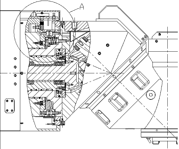
[0022] Such as figure 1 As shown, the embodiment of a universal milling head differential mechanism and machine tool in this technical solution is a schematic structural diagram of a 45-degree universal milling head, and the circle position A in the figure is a structural schematic diagram of the universal milling head differential mechanism in a universal milling head.

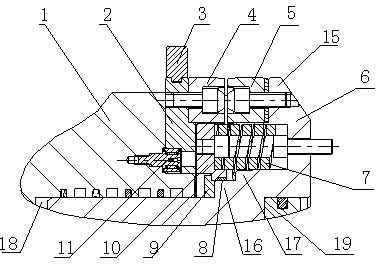
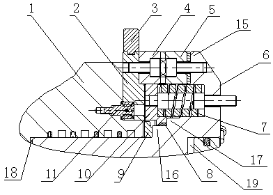
[0023] to combine figure 2 with image 3 Shown, the embodiment of a kind of universal milling head differential mechanism of this technical scheme is in the 45 degree universal milling head figure 1 Partial enlarged structural schematic diagram of A in the structural schematic diagram when the end sprocket is disengaged and engaged, including the main shaft (not shown in the figure), the first shaft sleeve (not shown in ...


PUM


Abstract

The invention discloses a universal cutter head differential mechanism and a machine tool, which belong to the field of a cutter head for a machine tool. The universal cutter head differential mechanism comprises a main shaft, a first shaft sleeve which is sleeved on the main shaft, a second shaft sleeve which is sleeved on the first shaft sleeve and a third shaft sleeve comprising a blind hole with a first stepped hole in one end, wherein the third shaft sleeve is sleeved outside the second shaft sleeve through the first stepped hole section and sleeved outside the first shaft sleeve through the blind hole section, one end of the second shaft sleeve, which is away from the third shaft sleeve, is provided with a radial ring-shaped first projection, one surface edge of the first projection, which faces towards the third shaft sleeve, is annularly provided with a first end fluted disc, one end surface of the third shaft sleeve, which faces towards the second shaft sleeve, is connected with an annular rotary disc, one surface edge of the rotary disc, which faces towards the second shaft sleeve, is annularly provided with a second end fluted disc, the first end fluted disc is opposite to the second end fluted disc, and the first end fluted disc and the second end fluted disc slide from the second shaft sleeve to a maximal stroke to be engaged with each other along the third shaft sleeve. The universal cutter head differential mechanism and the machine tool have beneficial effects that the precision of the cutter head is greatly improved and the minimal indexing reaches a decimal level and even the differentiating level.

Description

technical field [0001] The invention relates to a universal milling head, in particular to a differential mechanism of the universal milling head and a machine tool. Background technique [0002] As an important functional part of machine tools, universal milling head is widely used in various machine tools such as gantry, boring and milling. Among them, whether the indexing processing at different angles can be completed according to the processing requirements is the most important technical index to measure the universal milling head. According to the existing technology, the multi-angle machining of the universal milling head generally adopts the end tooth plate to achieve the purpose of precise indexing. It can be seen that the first problem that must be solved in the design of the universal milling head is how to use the end tooth plate for high efficiency. Highly reliable graduations. At present, domestic accessory head manufacturers have done little research on uni...

Claims


Application Information

Patent Timeline
Patent Type & Authority Patents(China)
IPC IPC(8): B23Q16/02B23Q1/25
Inventor 曹萍孟祥东郑开彬
Owner SANY GRP
Why Eureka
Try Eureka